- Automation & ControlView all 2,221 products
- Automation Accessories
- AC Drives
- PLC & I/O Cards
- Industrial Communications
- Vibration Monitoring
- Controllers & Data Acquisition
- Isolator & Barrier
- CCTV & Security
- Safety Switches & Guard Locking
- Encoders
- Motor Soft Starters
- HMI Displays
- Pneumatic Cylinders
- Industrial Computers
- Servo Drives
- Machine Vision
- Automation Software
- Robotics

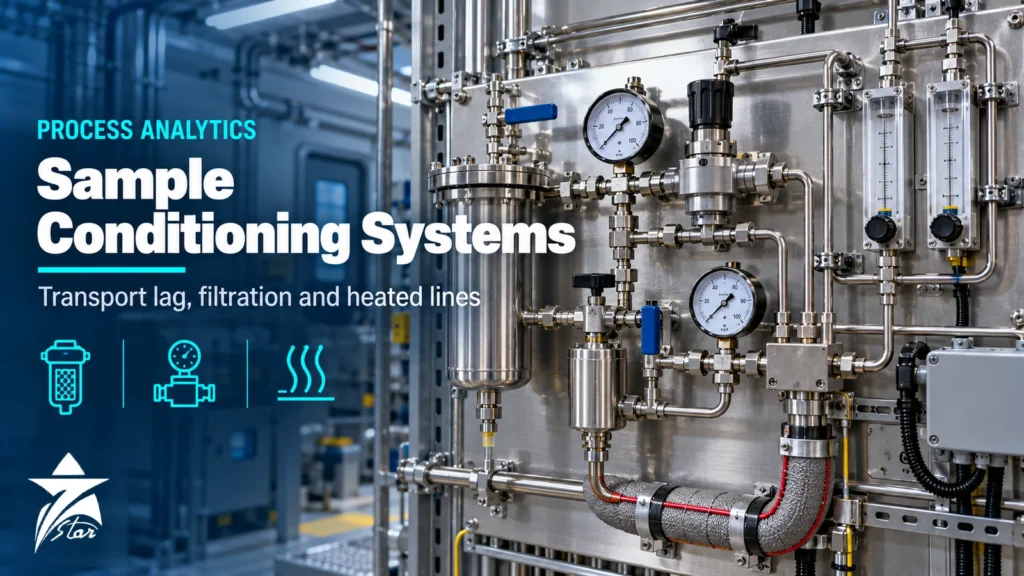
Analyzer engineers have a saying: the analyzer is only as good as the sample it receives. A well-calibrated oxygen, moisture, H₂S or chromatograph analyzer will report a precise but wrong number if the sample arrives late, condensed, contaminated or altered by adsorption. A properly designed sample conditioning system extracts a representative sample, moves it quickly to the analyzer, adjusts pressure, temperature and flow to what the analyzer needs, removes what would damage it, and returns or vents the sample safely. This guide covers transport lag calculation, fast loops, filtration, pressure reduction, heated lines and the design errors that most often make analyzer data untrustworthy.
The Five Jobs of a Sample Conditioning System
- Extract a sample that represents the process, using a probe positioned away from the pipe wall where liquids, scale and stratified layers collect.
- Transport it to the analyzer quickly enough that the result is still useful for control or protection.
- Condition it: reduce pressure, control temperature and flow, and remove particles or liquids the analyzer cannot accept, without changing the component being measured.
- Switch streams and introduce calibration or validation gas without cross-contamination.
- Dispose of the sample to a return point, flare or vent without back-pressure disturbances or safety issues.
API 555 on process analyzers and the ANSI/ISA-76.00.02 standard for modular sample system components (the basis of the NeSSI approach) are useful references when writing a specification. For natural gas sampling, API MPMS Chapter 14.1 and ISO 10715 give additional guidance.
Transport Lag: Why It Matters and How to Calculate It
Transport lag is the time the sample takes to travel from the tap to the analyzer. It is pure dead time added to every reading. A moisture analyzer used for dehydration control or an oxygen analyzer on a fired heater is of little use if the information is several minutes old. Many specifications set a target for total response time, including analyzer cycle time, that is in the order of a minute or two for control applications; whatever the target, it should be calculated, not assumed.
The basic calculation is simple: lag time equals the internal volume of the line divided by the actual volumetric flow at line conditions. For gases, actual flow depends on pressure, because flow meters on sample panels are normally calibrated at near-atmospheric conditions.
Worked example
- Tubing: 1/4 in OD × 0.035 in wall stainless, internal diameter about 4.6 mm, internal volume about 16 cm³ per metre. Line length 30 m gives about 490 cm³.
- Liquid sample at 1 L/min: velocity about 61 m/min, so lag is about 30 seconds.
- Gas sample at 10 barg (11 bar absolute) with 1 L/min measured at atmospheric pressure: actual flow in the line is only about 0.09 L/min, so lag rises to about 5.4 minutes.
- Same gas line after reducing pressure at the tap to about 0.5 barg: actual flow is about 0.67 L/min and lag falls to roughly 45 seconds.
The example shows the two main levers: reduce pressure as close to the tap as practical, and increase flow through a fast loop. Do not forget unswept volumes. Filter bowls, knock-out pots and oversized tubing add capacity lag that behaves like mixing, smearing a step change over a long time.
Fast Loops and Bypass Design
Analyzers typically need only a small flow. Running the whole transport line at that flow would make lag unacceptable, so a fast loop carries a much larger flow from the tap to a point near the analyzer and back to the process, and the analyzer takes a small slip stream from it.
- Drive the loop with a natural pressure difference: across a control valve, an orifice, a pump or a compressor stage. Check that the differential is available at minimum throughput, not just at design rate.
- Return the loop to a point that is always at lower pressure, or to flare if the process gas cannot be returned.
- Install a flow indicator with low-flow alarm on the loop; a blocked fast loop silently restores the long lag.
- Take the analyzer slip stream through a bypass (self-cleaning) filter so the fast loop sweeps collected particles away.
- For liquids, size the loop to keep velocities high enough to prevent solids settling.
Filtration and Phase Separation
The filter type should be matched to the contaminant and to the analyzer’s tolerance.
| Filter type | Removes | Typical position | Cautions |
|---|---|---|---|
| Bypass / inertial (self-cleaning) | Particles, carried back by the fast loop | At the fast loop take-off | Needs adequate bypass flow to self-clean |
| Particulate (sintered or wire mesh) | Solids above the rated size | Upstream of regulators and valves | Dead volume; collects liquids if not drained |
| Coalescing | Fine liquid aerosols, oil and water mist | Gas samples with entrained liquid | Requires a drain; may remove heavy components |
| Membrane (liquid-rejecting) | Liquids, passes only gas | Immediately before the analyzer | Membrane can blind; must be inspected |
| Knock-out pot / separator | Bulk liquid slugs | Wet gas services | Large volume adds lag and capacity effects |
Be careful about what filtration takes out. A coalescing filter on a sample whose heavy hydrocarbons are near their dew point removes exactly the components a chromatograph is trying to measure. Desiccant dryers obviously cannot be used before a moisture analyzer, and some filter media adsorb H₂S or water. Each component in the sample path must be judged against the measured species. Replacement filter elements and housings are available within our filter housings range.
Pressure Reduction and Joule-Thomson Cooling
Gas samples are often taken from lines at tens or hundreds of bar, but analyzers operate at near-atmospheric pressure. Every pressure drop cools natural gas by Joule-Thomson expansion; as a rule of thumb the effect is in the order of 0.5 °C per bar for typical natural gas, with the exact value depending on composition, pressure and temperature. A drop from 70 bar to 2 bar can therefore cool the gas by several tens of degrees, enough to condense heavy hydrocarbons and water or form hydrates.
- Reduce pressure at the probe with a probe-mounted regulator, so the transport line runs at low pressure and short lag.
- Use heated or vaporising regulators where the cooling would take the gas below its dew point; electrically heated or steam-heated bodies are both common.
- For liquefied gases such as LPG, use a vaporising regulator that fully flashes the liquid sample to avoid fractionation.
- Choose regulator materials and seats compatible with sour service where H₂S is present.
- Fit relief valves downstream of each pressure reduction to protect low-pressure components.
Seven Star LLC supplies sample and process pressure regulators including heated designs, on request.
Heated Lines and Temperature Control
If the sample has a dew point above the coldest temperature along the line, the line must be heated. Pre-insulated heat-traced tubing bundles, with self-regulating or constant-wattage tracing, keep the sample above dew point from the tap to the analyzer enclosure. Set the maintained temperature with a margin above the highest expected dew point, and remember that the sample also must not get too hot for elastomers, membranes or the analyzer inlet.
In the GCC, the issue is often reversed in summer: transport lines and panels in direct sun exceed analyzer inlet temperature limits, and plastic components degrade. Shade structures, insulated tubing bundles and temperature-controlled analyzer shelters solve both summer overheating and winter night-time condensation. For hot wet samples, such as stack gas or steam, a sample cooler or a chiller with condensate removal may be required before the analyzer, but only if the measured component is not soluble in the condensate.
Materials and Adsorption
Trace measurements are sensitive to the sample wetted surfaces. Stainless steel 316 is standard, but at ppm and ppb levels of H₂S, mercaptans or moisture, bare steel adsorbs and releases the component, slowing response and distorting readings. Inert-coated tubing and components, electropolished surfaces, minimal elastomers, and small tubing diameters help. Avoid plastics for oxygen and moisture measurement because of permeation, and avoid copper and brass in sulfur service.
Stream Switching, Calibration and Venting
- Use double block and bleed arrangements for stream switching to avoid cross-contamination between streams of different composition.
- Introduce calibration and validation gas as close to the analyzer as possible, ideally through the same path as the sample, so calibration checks the conditioning system too.
- Vent analyzer outlets to an atmospheric reference or an actively controlled back-pressure point; pressure fluctuations in a common vent or flare header change sample pressure and affect many analyzers.
- Keep vents and drains away from enclosure air intakes and observe hazardous area rules; see our hazardous area classification guide for zone and equipment considerations.
Common Sample Conditioning System Design Errors
- Running a long transport line at full process pressure with a tiny analyzer flow.
- Taking the sample from the bottom of a horizontal pipe where liquids and scale collect.
- Installing a large filter bowl with dead volume right before a fast-responding analyzer.
- Reducing pressure without heat, then wondering why the GC heating value is low.
- Connecting several analyzer vents to a common header with variable back-pressure.
- Using plastic tubing for oxygen or moisture samples.
Design and Specification Checklist
- Process conditions: pressure, temperature, composition, dew points, contaminants
- Measured component and range, and its sensitivity to adsorption or condensation
- Required response time, analyzer flow and inlet conditions
- Tap location, probe type and insertion length, with probe vibration check
- Fast loop drive pressure and return point
- Filtration, pressure reduction, heating and cooling requirements
- Stream switching, calibration gas and validation arrangement
- Vent and drain destinations, and hazardous area classification
- Enclosure or shelter environment and ambient design limits
Seven Star LLC supplies components for sample systems, including probes, filters, regulators and flow controls in the gas analyzer accessories range, as well as complete analyzer systems. For the analyzers themselves, see our process gas analyzer guide.
Sample System Components We Supply
These examples cover parts of a sample conditioning system.
| Product | Type | Where it fits |
|---|---|---|
| Swagelok KPR Series Regulator | Pressure regulator | Reducing sample pressure. |
| Swagelok SS-4F-2 Inline Particulate Filter, 2 Micron | Inline particulate filter | Removing particles. |
| Swagelok SS-4TF-7 Tee-Type Filter, 7 Micron | Tee-type filter | Removing particles. |
| Swagelok SS-4MG Medium-Flow Metering Valve | Metering valve | Controlling sample flow. |
| Swagelok SS-RL3S4 Low-Pressure Proportional Relief Valve | Relief valve | Overpressure protection. |
| Swagelok DOT Sample Cylinder, Double-Ended and Single-Ended | Sample cylinder | Spot samples. |
Send the analyser, sample conditions and required components through our quote request form.
Sourcing Sample Conditioning Components Through Seven Star LLC
Seven Star LLC supplies sample probes, heated regulators, membrane and coalescing filters, valves, flowmeters and heated tubing on request for analyzer systems in refineries, gas plants, power and petrochemical facilities across Oman and the GCC. We help with selection and cross-checking part numbers for components from manufacturers such as Swagelok, Parker, Genie (A+ Corporation) and Welker. Availability and lead time are confirmed at quotation.
Send your sample system drawing, analyzer datasheet or bill of materials with your RFQ, and we will return a component-by-component offer with matching part numbers.
Frequently asked questions
How do I calculate analyzer sample transport lag?
Divide the internal volume of the sample line by the actual volumetric flow at line pressure and temperature. For gases, correct the flow measured at atmospheric conditions for line pressure, because higher pressure means lower actual velocity and longer lag. Add allowance for unswept volumes such as filter bowls.
What is a fast loop in an analyzer sample system?
A fast loop is a high-flow sample circuit from the process tap to near the analyzer and back to a lower-pressure point. The analyzer takes a small slip stream from it, so transport lag is short even though the analyzer itself uses little sample.
Why do gas samples need heated regulators?
Pressure reduction cools gas by the Joule-Thomson effect, roughly 0.5 °C per bar for typical natural gas. Without heat, the gas can fall below its hydrocarbon or water dew point, condense heavy components and give wrong readings, or form hydrates that block the regulator.
Which filter should be installed directly before an analyzer?
A membrane-type liquid-rejecting filter is commonly used immediately upstream of gas analyzers, because it passes gas but stops liquid carry-over. Check that the membrane material does not adsorb or react with the measured component.
Can sample tubing material affect analyzer readings?
Yes. At trace levels, H₂S, mercaptans and moisture adsorb on bare steel, delaying response and distorting values. Inert-coated or electropolished tubing is used for trace sulfur and moisture, and plastics are avoided for oxygen and moisture because of permeation.
Why should analyzer vents not share a common header without control?
Many analyzers are sensitive to outlet pressure. Pressure fluctuations in a shared vent or flare header change the sample pressure inside the analyzer and cause reading shifts. Use an atmospheric reference vent or back-pressure control on the outlet.
Was this guide helpful?One click helps us write better guides for engineers.
Thank you! Glad it helped. Need this equipment for your project? Request a quotation
Thank you. We will use this to improve the guide.