- Automation & ControlView all 2,220 products
- Automation Accessories
- AC Drives
- PLC & I/O Cards
- Industrial Communications
- Vibration Monitoring
- Controllers & Data Acquisition
- Isolator & Barrier
- CCTV & Security
- Safety Switches & Guard Locking
- Encoders
- Motor Soft Starters
- HMI Displays
- Pneumatic Cylinders
- Industrial Computers
- Servo Drives
- Machine Vision
- Automation Software
- Robotics


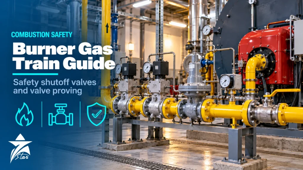
Most serious incidents in fired equipment start with fuel where it should not be: gas leaking through a closed valve into a cold furnace, or an ignition attempt into a chamber that was never purged. The burner gas train is the set of valves, regulators, switches and controls between the gas supply and the burner, and its job is to deliver the right flow during firing and to isolate fuel reliably at every other moment. This guide explains the components of a typical gas train, how safety shutoff valves and valve proving work, the main requirements found in EN 676 and NFPA 85 and 86, and what to check when specifying, maintaining or replacing parts on boilers, heaters and furnaces.
What a Burner Gas Train Does
A gas train performs four functions in sequence: it cleans the gas, reduces and stabilises its pressure, proves that the conditions for safe firing exist, and shuts off fuel automatically when any of those conditions is lost. The burner management system (BMS) or burner control unit sequences the train: pre-purge, ignition, flame proving, modulation and post-purge. Every component in the train exists to support one of those steps, and removing or bypassing any of them changes the safety basis of the installation.
Typical Gas Train Components in Flow Order
- Manual isolation valve: a lockable quarter-turn valve at the train inlet for maintenance isolation.
- Gas filter or strainer: protects valve seats and regulators from pipe scale, welding debris and dust; a differential pressure gauge shows when the element needs changing.
- Pressure regulator: reduces supply pressure to the burner’s required inlet pressure and holds it steady as flow changes; some designs include over-pressure shutoff or relief.
- Low gas pressure switch: stops or prevents firing if inlet pressure falls below the minimum for stable combustion.
- Two automatic safety shutoff valves in series: the primary fuel isolation, closed by spring when de-energised.
- Valve proving system or vent valve: confirms the shutoff valves are tight, or vents the space between them, depending on the design and code.
- High gas pressure switch: trips the burner if pressure downstream of the regulator rises above a safe limit.
- Flow control valve or butterfly: modulates gas flow in step with combustion air, either through mechanical linkage or electronic ratio control.
- Pilot or ignition gas line: its own regulator and shutoff valves feeding the igniter on burners that use a pilot.
Packaged monoblock burners often combine the regulator, filter and two shutoff valves in one multi-function valve body. Larger industrial and utility burners use individual components assembled on a skid, which makes each item easier to inspect and replace but adds joints and leak paths.
Safety Shutoff Valves: How They Fail Safe
Automatic safety shutoff valves are normally closed and held open by power: a solenoid, or a motorised or hydraulic actuator that compresses a closing spring. On loss of power from the flame safeguard or any limit in the safety chain, the spring closes the valve without relying on electricity or compressed air. In Europe these valves are tested to EN 161, which defines classes based on closing force and seat tightness; Class A valves are the type normally required for main gas shutoff. In North America, listings to standards such as UL 429 or FM approval serve a similar role.
Two valves are installed in series so that a single failure, such as debris on one seat or a broken spring, does not leave gas flowing into a shut-down burner. Slow-opening actuators help light-off by ramping flow, but closing must always be fast. When ordering replacements, match the valve class, voltage, pressure rating, connection size, closing time and any proof-of-closure switch that the BMS expects; a valve that looks identical but lacks the closed-position switch may stop the burner from starting or, worse, remove a check the system relies on.
Valve Proving Systems and Double Block and Bleed
Two valves in series only help if both are tight. Two common approaches confirm this.
Valve proving (leak testing)
A valve proving system, defined in Europe by EN 1643, tests the shutoff valves before start-up, after shutdown, or both. A typical sequence closes both valves, briefly opens the downstream valve to vent the interspace, closes it, and watches a pressure switch for a set time: a rise in pressure means the upstream valve leaks. It then briefly opens the upstream valve to pressurise the interspace, closes it, and watches for a pressure fall, which would mean the downstream valve leaks. If either test fails, the burner locks out. EN 676 requires a valve proving system for burners above 1200 kW, and many owners fit one on smaller units as well.
Double block and bleed
Common in installations designed to NFPA 85 and NFPA 86, double block and bleed places a normally open vent valve between the two shutoff valves, piped to a safe location outdoors. When the shutoff valves close, the vent opens, so any gas passing the upstream valve is vented rather than accumulating against the downstream valve. Venting releases gas to atmosphere, so vent line sizing, termination point and hazardous area classification around the outlet must be addressed. Some codes accept valve proving as an alternative to the vent arrangement; the applicable edition and the authority having jurisdiction decide.
EN 676, NFPA 85 and NFPA 86 in Brief
| Item | EN 676 | NFPA 85 | NFPA 86 |
|---|---|---|---|
| Scope | Automatic forced-draught burners for gaseous fuels | Boiler and combustion systems hazards, including single and multiple burner boilers above a stated input | Ovens and furnaces, including process heaters and thermal oxidisers |
| Typical users | Burner manufacturers certifying packaged burners in Europe and markets that follow EN | Power plant and large industrial boiler owners, designers and insurers | Process heating equipment designers and owners |
| Gas shutoff | Two automatic shutoff valves in series, class and closing requirements by capacity | Two safety shutoff valves with proof of closure; vent or proving arrangement | Two safety shutoff valves; valve proving or vent alternatives depending on capacity |
| Valve proving | Required above 1200 kW | Recognised option, often as an alternative to venting | Recognised option for listed arrangements |
| Purge | Pre-purge requirements set in the standard | At least 5 minutes or 5 volume changes; multiple burner boilers at not less than 25% of full-load airflow | Purge of the combustion chamber and connected flue passages before ignition |
These documents are revised regularly, and requirements change between editions. Always confirm which edition the project, the insurer or the local authority has adopted, and treat the table as orientation rather than a design basis. Projects in the GCC often reference NFPA for oil, gas and power facilities and EN for packaged burners from European manufacturers, so the same site may hold equipment built to both.
Purge, Ignition and Flame Supervision
- Pre-purge: airflow through the furnace before ignition removes any combustible gas. Airflow must be proven by a switch or transmitter, and dampers proven open, before the purge timer runs.
- Trial for ignition: pilot or main flame must be detected within a short, fixed safety time, or the burner locks out and requires a new purge before retrying.
- Flame supervision: UV, infrared or flame rod detectors with self-checking amplifiers where burners run continuously, since a stuck detector could report a flame that is not there.
- Post-purge: clears residual fuel after shutdown, especially important on heaters with many burners.
On larger multi-burner boilers and heaters, the BMS is often implemented in a safety PLC to a required safety integrity level. The principles behind that approach are covered in our article on safety instrumented systems and SIL-rated safety PLCs.
Sizing and Specification Data
- Fuel type and composition (natural gas, LPG, refinery fuel gas), with heating value, specific gravity and any H2S, moisture or liquids.
- Maximum and minimum burner firing rates and the required turndown.
- Available supply pressure range at the train inlet and required pressure at the burner head.
- Pipe size, connection type and pressure rating of each component.
- Electrical supply, enclosure rating and hazardous area classification for valves, switches and actuators.
- Applicable code (EN 676, NFPA 85, NFPA 86 or local) and whether valve proving or vent valves are required.
- Existing burner control or BMS model and the signals it expects, such as proof of closure and pressure switch contacts.
Pressure drop across the filter, regulator, shutoff valves and flow control valve at maximum firing must leave enough pressure at the burner head. Undersized trains are a common reason a burner cannot reach full output on cold mornings or when supply pressure sags at peak demand.
GCC Site Conditions
High ambient temperatures affect solenoid coils, actuator electronics and pressure switch diaphragms, so check temperature ratings for outdoor trains in direct sun. Dust and sand accelerate filter loading and can foul vent valve outlets and switch breather ports. Refinery and gas plant fuel gas may carry H2S and liquids; seat and diaphragm materials must suit sour gas, and knock-out pots or coalescers upstream of the train protect regulators. In classified areas, solenoids, switches and actuators need suitable certification for the zone and gas group.
Common Faults and Maintenance
- Valve proving lockouts: often a real seat leak caused by debris, but also failed pressure switches or incorrect test times after component replacement.
- Regulator creep or hunting: worn diaphragms or seats, or a regulator oversized for low-fire flow.
- Low gas pressure trips at high fire: clogged filters, undersized pipework or supply pressure drop.
- Nuisance flame failures: dirty detector sight glasses, ageing UV tubes or poor flame stability from incorrect air-fuel ratio.
- Bypassed or jumpered switches left after troubleshooting, which remove protection without anyone noticing.
Maintenance should follow the burner manufacturer’s schedule and the site’s inspection programme: periodic functional tests of every safety interlock, tightness tests of shutoff valves, filter element changes based on differential pressure, regulator set-point checks and combustion analysis. Keep records of each test, and replace safety components with parts of the same approval and rating rather than visually similar alternatives.
Gas Train Inspection Checklist
- Manual isolation valve operates and can be locked.
- Filter differential pressure within the acceptable range.
- Regulator outlet pressure stable from low to high fire.
- Low and high gas pressure switches trip at their set points.
- Both safety shutoff valves close on loss of power and proof-of-closure switches work.
- Valve proving or vent valve sequence completes correctly.
- Purge airflow and damper position proven before the purge timer starts.
- Flame detector responds to flame loss within the safety time.
- No bypasses or jumpers present in the safety chain.
Burner and Gas Train Products We Supply
These examples cover gas trains, valve proving and flame safeguard products.
| Product | Type | Where it fits |
|---|---|---|
| DUNGS MB-DLE 407 B01 S50 GasMultiBloc Rp 3/4, 230 V | GasMultiBloc | Compact gas trains. |
| DUNGS DMV-D 5125/11 ECO Gas Double Solenoid Valve | Double solenoid valve | Gas shut-off. |
| DUNGS VPS 504 S04 Valve Proving System 230 V (219881) | Valve proving system | Leak testing of the gas safety valves. |
| DUNGS GW 150 A6 Gas Pressure Switch 5-150 mbar | Gas pressure switch | Low and high gas pressure limits. |
| LAMTEC BurnerTronic BT300 Burner Control System | Burner control system | Burner sequencing. |
| Fireye InSight 95DSS2 UV/IR Integrated Flame Scanner | UV/IR flame scanner | Flame supervision. |
Send the burner model, gas type, pressure and capacity through our quote request form.
Sourcing Burner Gas Train Components Through Seven Star LLC
Seven Star LLC supplies burners and gas train components, including gas solenoid valves, pressure regulators, pressure switches, valve proving units and flame detectors, on request for boilers, heaters and furnaces across Oman and the GCC. We help with selection and cross-checking part numbers against your existing train; availability and lead time are confirmed at quotation. Related combustion items are listed under HVAC and combustion.
Send the burner nameplate, a photo or piping diagram of your gas train, or your RFQ, and we will match each component for your review.
Frequently asked questions
What components are in a burner gas train?
A typical train has a manual isolation valve, filter, pressure regulator, low gas pressure switch, two automatic safety shutoff valves in series, a valve proving system or vent valve, a high gas pressure switch and a flow control valve. Burners with a pilot also have a separate pilot gas line with its own regulator and shutoff valves.
When is a valve proving system required?
EN 676 requires a valve proving system on forced-draught gas burners above 1200 kW. NFPA 85 and NFPA 86 recognise valve proving as an option in certain arrangements, often as an alternative to a vent valve. The applicable edition and the authority having jurisdiction decide what is mandatory for a specific installation.
What is the difference between valve proving and double block and bleed?
Valve proving tests the tightness of both shutoff valves by watching pressure in the space between them, and locks out the burner if either leaks. Double block and bleed instead opens a vent valve between the two shutoff valves when they close, so any leakage is discharged to a safe location rather than reaching the burner.
How long is the purge before ignition under NFPA 85?
NFPA 85 calls for a purge of at least 5 minutes or 5 volume changes of the boiler enclosure, whichever is longer, with airflow proven. For multiple burner boilers the purge airflow must be at least 25% of full-load airflow. Check the edition adopted for your project.
Why does a gas train lock out on valve proving?
The most common cause is a real seat leak on one shutoff valve, often from debris after pipework changes. Faulty or mis-set pressure switches, incorrect test times after replacing components, and supply pressure fluctuations can also trigger lockouts. Investigate before resetting repeatedly.
Can I replace a gas safety shutoff valve with a similar-looking model?
Only if it has the same approval class, pressure rating, voltage, connection, closing time and proof-of-closure features that the burner control expects. A visually similar valve without the same rating or closed-position switch can change the safety basis of the burner. Cross-check the full part number and approvals before ordering.
Was this guide helpful?One click helps us write better guides for engineers.
Thank you! Glad it helped. Need this equipment for your project? Request a quotation
Thank you. We will use this to improve the guide.