- Automation & ControlView all 2,221 products
- Automation Accessories
- AC Drives
- PLC & I/O Cards
- Industrial Communications
- Vibration Monitoring
- Controllers & Data Acquisition
- Isolator & Barrier
- CCTV & Security
- Safety Switches & Guard Locking
- Encoders
- Motor Soft Starters
- HMI Displays
- Pneumatic Cylinders
- Industrial Computers
- Servo Drives
- Machine Vision
- Automation Software
- Robotics











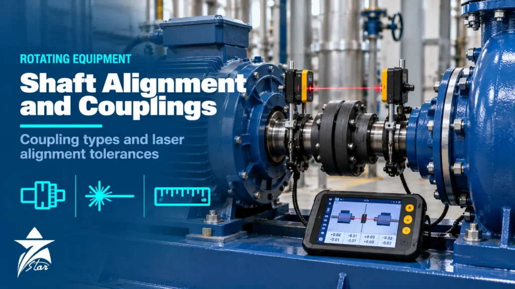
A coupling joins two shafts so that torque flows from a driver to a driven machine, but the way it is selected and installed decides how long the bearings, seals and the coupling itself will last. Misalignment is one of the most common causes of vibration and premature bearing and seal failures on pumps, fans and compressors. This guide compares the main flexible coupling types and then covers shaft coupling alignment: what offset and angularity mean, which tolerances to use, how to deal with soft foot and thermal growth, and how to carry out a laser alignment that holds once the machine is running.
What a Flexible Coupling Must Do
A flexible coupling transmits torque while accommodating small misalignments between shafts, axial movement from thermal expansion or motor end float, and in many designs, torsional shocks and vibration. It is also a deliberate weak link in some drives, protecting expensive equipment if something jams. What it should not be asked to do is compensate for poor installation. Every misalignment the coupling absorbs is converted into reaction forces on the shafts and bearings, and the coupling elements wear or fatigue faster as well.
Coupling Types Compared
| Coupling type | How it flexes | Lubrication | Torsional behaviour | Typical uses |
|---|---|---|---|---|
| Jaw (spider) | Elastomer spider between claw hubs | None | Damping, some backlash as spider wears | Small motors, pumps, fans, gear motors |
| Tyre | Rubber tyre element in shear | None | Very soft, high damping, large misalignment capacity | Conveyors, pumps with shock loads |
| Pin and bush | Elastomer bushes on pins | None | Damping | General industrial drives |
| Gear | Crowned external teeth in internal sleeve | Grease or oil | Torsionally stiff, compact, very high torque | Mills, cranes, large fans, older turbomachinery |
| Disc (laminated membrane) | Thin steel disc packs flex | None | Torsionally stiff, no backlash | API process pumps, compressors, turbines |
| Grid | Tapered steel grid in grooved hubs | Grease | Torsional flexibility with shock damping | Crushers, conveyors, mixers, large pumps |
| Rigid (flange, sleeve) | Does not flex | None | Stiff | Shafts that must act as one, aligned with great precision |
Elastomeric couplings are forgiving and cheap to maintain, and the elastomer element is the planned wear part. Watch the temperature limit of the elastomer in hot plant rooms and outdoor skids, and protect it from oil and ozone. Gear couplings pack high torque into a small diameter, and a double-engagement design accepts parallel offset, but they need regular lubrication and the teeth wear quickly if alignment is poor. Disc couplings have no rubbing parts and need no lubrication, which is why they dominate spacer couplings on process pumps and turbomachinery. Grid couplings combine metal strength with some torsional flexibility and absorb shock well, but need their covers sealed and greased.
Spacer Couplings and Shaft Locking Devices
A spacer coupling places a removable spool between the hubs. On end-suction process pumps it allows the back pull-out assembly, including the impeller and seal, to be removed without moving the motor or the pipework, which keeps the motor alignment undisturbed. The distance between shaft ends must match the pump and motor drawing.
Hubs are attached by keys with interference fits, by taper bushes, or by keyless shaft locking devices that clamp through conical rings. Locking devices transmit torque by friction, allow fine axial and angular positioning, and avoid keyway stress concentrations, but need correct screw torque and clean, dry or lightly oiled surfaces according to the manufacturer’s instructions. Our couplings and shaft locking devices category shows typical types.
Coupling Selection Criteria
- Nominal torque: T (N·m) = 9,550 × P (kW) / n (rpm), multiplied by a service factor for the driver and driven machine.
- Peak and reversing torques: start-ups, direct-on-line motors and reciprocating machines produce peaks well above nominal.
- Speed and balance: high-speed couplings need a suitable balance grade and must not exceed the coupling’s maximum speed.
- Bore sizes, keyways and the fitting method on both shafts.
- Distance between shaft ends and available space.
- Misalignment and axial float capacity, including motor magnetic centre on sleeve bearing motors.
- Environment: temperature, oil, chemicals, dust and the need for hazardous area suitability.
- Maintenance: lubricated or lubrication-free, and how the wear element is replaced.
Understanding Misalignment: Offset and Angularity
Shafts can be misaligned in two ways, and both occur in the vertical and horizontal planes. Offset (parallel) misalignment is the distance between the shaft centrelines, normally measured at the coupling centre. Angular misalignment is the difference in slope between the two centrelines, expressed as a gap difference across the coupling face per unit of diameter, for example millimetres per 100 mm, or as a slope. Real machines almost always have a combination, and the correction moves have to be calculated for both feet pairs of the movable machine.
Alignment Tolerances by Speed
Tolerances should come first from the equipment manufacturer or site specification. Where none exist, speed-based tables are widely used. The values below, for short flexible couplings, are taken from a table published by the US Department of Energy motor systems programme, originally from alignment specialist Ludeca, converted from mils and rounded. Treat them as the maximum deviation from the target alignment, which may include thermal growth offsets.
| Speed (rpm) | Offset, excellent | Offset, acceptable |
|---|---|---|
| 900 | 0.08 mm (3.0 mils) | 0.15 mm (6.0 mils) |
| 1,200 | 0.06 mm (2.5 mils) | 0.10 mm (4.0 mils) |
| 1,800 | 0.05 mm (2.0 mils) | 0.08 mm (3.0 mils) |
| 3,600 | 0.025 mm (1.0 mil) | 0.04 mm (1.5 mils) |
Angularity tolerances are given in similar tables as gap difference per coupling diameter, and they tighten with speed in the same way. For spacer couplings, tolerances are expressed per unit length of spacer. Tighter tolerances are justified on high-power or critical machines, and rigid couplings must be aligned as accurately as possible because they accept no misalignment at all.
Preparing the Machine: Soft Foot, Pipe Strain and Run-Out
Most alignment jobs that fail do so before the first reading. Check these points first:
- Soft foot: with all bolts tight, loosen one foot at a time and measure how far the shaft or foot moves. A practical guide from one alignment instrument maker recommends correcting any foot above about 0.08 mm (3 mils); many site standards use 0.05 mm.
- Shims: use clean, stainless, pre-cut shims and keep the number under each foot to a minimum, ideally no more than three.
- Pipe strain: watch the pump shaft with an indicator while the suction and discharge flanges are unbolted; movement means the pipework is pulling the pump out of position.
- Base condition: cracked grout, corroded baseplates and loose anchor bolts make alignment unstable.
- Coupling and shaft run-out: excessive run-out falsifies readings and indicates a bent shaft or poorly bored hub.
- Bolt-bound feet: check that the movable machine has room to move horizontally before starting.
Laser Alignment Step by Step
- Lock out and isolate both machines, and verify zero energy.
- Clean feet and base, correct soft foot and check pipe strain.
- Mount the laser heads on the shafts, not on the coupling flexible element.
- Enter the dimensions: coupling centre, sensor spacing and foot positions.
- Take readings by rotating both shafts together through at least the minimum arc the system requires.
- Enter thermal growth targets if the machines run hot or cold.
- Correct vertical alignment with shims, then horizontal alignment with jacking bolts.
- Tighten foot bolts in sequence and re-measure to confirm the result.
- Record the final readings, shim packs and soft foot values for the next overhaul.
Thermal Growth and Hot Climate Effects
Machines rarely run at the temperature they are aligned at. A pump handling hot condensate, a steam turbine or a compressor grows upward and sometimes sideways as it heats, while the motor grows by a different amount. The cold alignment target must offset this so the shafts line up in operation. Manufacturer data is the best source; otherwise use calculated values based on centreline height, material and temperature rise, and confirm with hot checks where the machine is critical. In GCC summers, outdoor skids heated by direct sun can show different growth from the morning to the afternoon, so align at a consistent time of day and avoid mixing readings taken in different conditions. Sand and dust also accelerate wear of lubricated gear and grid couplings with damaged seals, so inspect covers and lubricant at each check.
Common Coupling and Alignment Mistakes
- Aligning to the coupling’s maximum misalignment capacity instead of a proper tolerance.
- Ignoring soft foot or using many thin, rusted shims.
- Aligning a pump while pipework is still forcing it out of position.
- Forgetting thermal growth on hot service pumps and turbines.
- Hammering hubs onto shafts, which damages bearings in the motor.
- Mixing elastomer elements from different coupling manufacturers.
- Neglecting lubrication on gear and grid couplings.
Verifying the Shaft Coupling Alignment Result
After alignment, run the machine and compare vibration with the previous baseline. Misalignment often shows as elevated vibration at twice running speed and high axial vibration, although these signatures overlap with other faults. Trend vibration and bearing temperatures after the work; our guide to vibration monitoring systems explains online, wireless and portable options.
Shaft Coupling Alignment Checklist
- Coupling type and size confirmed for torque, speed and bores.
- Manufacturer or site alignment tolerance identified.
- Base, grout and anchor bolts in good condition.
- Soft foot measured and corrected.
- Pipe strain checked and removed.
- Thermal growth targets entered.
- Final offset and angularity within tolerance in both planes.
- Results recorded and vibration baseline taken after start-up.
Couplings and Alignment Tools We Supply
These products cover the coupling types compared above, plus the tools to check alignment after installation.
| Product | Type | Where it fits |
|---|---|---|
| KTR ROTEX Torsionally Flexible Jaw Coupling | Jaw coupling | Small pumps, fans and gearboxes with moderate misalignment. |
| Lovejoy 1060 Grid Coupling, Horizontal Split Cover | Grid coupling | Medium and heavy drives that need shock absorption. |
| Flender ZAPEX ZW Gear Coupling | Gear coupling | High torque in compact space, such as mill and crane drives. |
| Flender N-ARPEX All-Steel Multi-Disk Coupling | All-steel disc coupling | Pumps and compressors that must run without lubrication. |
| Dodge StratoLink D71 API 610 Disc Coupling | API 610 disc coupling | Process pumps built to API 610. |
| SKF TKSA 41 Laser Shaft Alignment Tool | Laser shaft alignment tool | Checking and correcting shaft alignment after installation. |
For a replacement coupling, send the make, size and bore details. For a new drive, send the power, speed and shaft sizes through our quote request form.
Sourcing Couplings and Alignment Items Through Seven Star LLC
Seven Star LLC supplies flexible couplings, spare elements, shaft locking devices and related bearings and power transmission products from established manufacturers on request, as well as pumps and motor spares. We help with selection and with cross-checking coupling part numbers and element sizes, and availability and lead time are confirmed at quotation.
Send us the coupling make and size, shaft bores, motor power and speed, or a photo of the nameplate and coupling, and we will respond with matching options in our quotation.
Frequently asked questions
If a flexible coupling can accept misalignment, why align the shafts accurately?
A coupling's published misalignment capacity is the limit for the coupling itself, not for the machine. Misalignment the coupling accepts still produces reaction forces that load the bearings, seals and shafts, increase vibration and raise temperature. Aligning to tolerances much tighter than the coupling limit protects the bearings and seals of both machines.
What alignment tolerance should I use for a 1,500 or 3,000 rpm pump?
Use the equipment manufacturer's or site specification first. Without one, published speed-based tables for short flexible couplings are a good guide: for example, one widely reproduced table allows an offset of about 0.05 mm excellent and 0.08 mm acceptable at 1,800 rpm, tightening to about 0.025 mm and 0.04 mm at 3,600 rpm. Interpolate for 1,500 and 3,000 rpm and treat the values as maximum deviation from the target.
What is soft foot and how much is acceptable?
Soft foot is a condition where a machine foot does not sit flat on its base, so tightening the bolt distorts the machine frame. It changes alignment readings and puts stress on bearing housings. One leading alignment guide recommends correcting any foot that moves more than about 0.08 mm (3 mils) when loosened; many site specifications are tighter, around 0.05 mm.
When should I choose a disc coupling over a gear coupling?
Disc couplings need no lubrication, have no wearing parts when correctly aligned and are torsionally stiff with no backlash, which makes them the usual choice for API process pumps, compressors and turbomachinery. Gear couplings carry very high torque in a compact size but need regular lubrication and wear if misaligned. Gear couplings remain common in heavy industrial drives such as mills and cranes.
What is thermal growth compensation in alignment?
Machines grow as they warm up, and pumps, motors, turbines and compressors grow by different amounts. The cold alignment target is therefore offset so the shafts become aligned at operating temperature. The offsets come from the manufacturer, calculations based on temperature and centreline height, or hot alignment checks.
Is laser alignment always better than dial indicators?
Laser systems are faster, avoid indicator bar sag and calculate corrections automatically, which reduces human error. The reverse dial indicator method can be equally accurate when done carefully and is still a valid method. The bigger gains usually come from correcting soft foot, pipe strain and thermal growth, whichever measuring method is used.
Was this guide helpful?One click helps us write better guides for engineers.
Thank you! Glad it helped. Need this equipment for your project? Request a quotation
Thank you. We will use this to improve the guide.