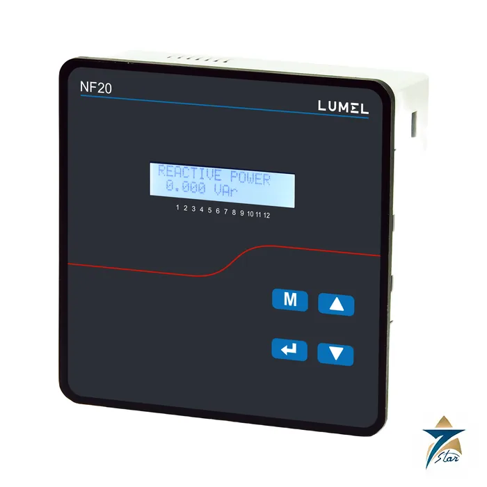
The Lumel NF20 is an automatic power factor controller that switches capacitor banks in and out to hold a target power factor. It comes in a 96 x 96 mm case with 4, 6 or 8 relay steps and a 144 x 144 mm case with 6, 8 or 12 steps, so one family covers small compensation panels as well as large ones. It also works as a network analyser: it measures about 73 electrical parameters over Modbus and true r.m.s. harmonics up to the 31st.
Why power factor correction needs a controller like the NF20
Most industrial loads in Gulf plants, such as induction motors, chillers and pumps, draw lagging reactive current, and utilities penalise a low power factor. The NF20 measures the network, calculates how many kvar are missing against the target power factor, and connects the matching capacitor steps. Four-quadrant operation lets it behave correctly when the site exports power, for example with generators in parallel. Programmable switch-in, switch-off and discharge times protect the capacitors, and the controller records each bank’s switching count and operating hours so ageing banks can be spotted.
Key features from the data sheet
- 4, 6 or 8 switching outputs in the 96 x 96 mm case; 6, 8 or 12 in the 144 x 144 mm case.
- Alarm relay with warning messages and a programmable kvar value for each bank.
- Wide voltage measuring input of 30 to 550 V a.c. (L-L or L-N), accuracy 0.5%.
- Wide auxiliary supply of 110 to 550 V a.c./d.c. as quoted in the features list.
- 2 x 16 character LCD, true r.m.s. measurement to the 31st harmonic, THD of voltage and current.
- Optional RS-485 Modbus and optional real-time clock.
Technical specification
Control and measurement
| Parameter |
Specification |
| Number of outputs |
Up to 8 (96 x 96 mm) or up to 12 (144 x 144 mm) |
| Alarm output |
1 relay, maximum 250 V a.c. / 1000 W |
| Target power factor range |
0.8 inductive to 0.8 capacitive |
| Switching threshold |
30 to 100% |
| Switch-in / switch-off time |
10 to 1800 s each |
| Discharge time |
60 to 1800 s |
| Nominal input voltage / current |
240 V a.c.; 1 A or 5 A a.c. |
| CT primary / secondary |
Primary 1 to 9999 A; secondary 1 A or 5 A programmable |
| Voltage / current measuring range |
30 to 550 V a.c.; current 2 mA start, 10 mA operating, 6 A maximum |
| Frequency |
40 to 70 Hz, error 0.15% of mid frequency |
| Accuracy |
Voltage and current 0.5%; active, reactive and apparent power 1.0%; active and apparent energy 1.0%; reactive energy 2.0%; THD 4.0% |
| Continuous input current |
120% of rated value |
Supply, environment and construction
| Parameter |
Specification |
| Supply |
110 to 550 V a.c., 40 to 70 Hz, below 10 VA |
| Burden |
Voltage below 0.2 VA per phase; current below 0.6 VA per phase |
| Overload |
Voltage 2 x rated for 1 s, repeated 10 times; current 20 x for 1 s, repeated 5 times at 5 min |
| Operating / storage temperature |
-10 to +60 degrees C / -20 to +65 degrees C |
| Relative humidity |
0 to 90%, non-condensing; warm-up at least 3 min |
| Shock / vibration |
15 g in 3 planes; 10 to 55 Hz, 0.15 mm amplitude |
| Protection |
IP54 from the front, IP20 from the terminal side |
| Dimensions and cut-out |
96 x 96 x 51 mm (75 mm with extension modules), cut-out 92 +0.8 mm; 144 x 144 x 56 mm, cut-out 138 x 138 mm |
| Weight |
0.35 kg (96 x 96 mm); 0.5 kg (144 x 144 mm) |
| Standards named |
EMC IEC 61326-1:2012; accuracy IEC 62053-21; safety IEC 61010-1-2010; IP IEC 60529; pollution degree 2; installation category III; 2.2 kV a.c. for 1 min test |
| Serial interface |
RS-485, MODBUS RTU 8N2, 8E1, 8O1, 8N1, address 1 to 247, 4.8 to 115.2 kbit/s |
Decoding the NF20 ordering code
The 96 x 96 mm code reads NF20 A 1 H X X X X X 000 X X and the 144 x 144 mm code reads NF20 B 1 H X A X X 0 000 X X. A or B is the size, 1 is the 240 V input, H the 110 to 550 V a.c. supply, then come the relay steps (4, 6 or 8; or 6, 8 or 12), the alarm output (A), RS-485 (R with, Z without), real-time clock (R or Z), the adaptor plate for the small case (0 without, 1 with), the standard version 000, the language (P Polish, E English) and the acceptance test (0 none, 1 inspection certificate, 2 calibration certificate). Per the data sheet, 6 steps in the small case are of limited availability, and RS-485 is only available on the 8-step small case or the 12-step large case.
Commissioning and operation notes from the manual
The controller mounts in a panel with a 92 x 92 mm cut-out (96 mm model) or 138 x 138 mm (144 mm model) and clips in with four retention clips. Menu access is password protected, and the manual provides a factory-default reset and a test-run menu for the capacitor outputs. Protective warnings cover over- and under-voltage, over-current, over-temperature (55 and 60 degrees C limits are factory set), THD limits and capacitor-bank faults, each with a trip delay that is factory set. Set the CT ratio and the kvar of the smallest bank before enabling automatic mode.
Use in GCC capacitor panels
The NF20 suits automatic capacitor banks in factory, desalination, mall and camp switchrooms, where the -10 to +60 degrees C operating rating gives margin in hot plant rooms. Plants with heavy harmonic content from drives should use the THD readings and warnings, and detuned reactors where required by the bank design.
Frequently asked questions
How many capacitor steps can the NF20 control?
Up to 8 in the 96 x 96 mm case and up to 12 in the 144 x 144 mm case.
What voltage can the NF20 measure?
30 to 550 V a.c., line-to-line or line-to-neutral, with 0.5% accuracy.
Does the NF20 have Modbus?
RS-485 Modbus RTU is optional; it is only available on the 8-step 96 x 96 mm and the 12-step 144 x 144 mm versions.
Which harmonics does it measure?
True r.m.s. measurement up to the 31st harmonic, with THD for voltage and current.
What is the target power factor range?
0.8 inductive to 0.8 capacitive.
Documents and quotation
Our Muscat office quotes the NF20 as an independent supplier, with price, lead time and stock given per request. The Lumel NF20 data sheet NF20-19 is attached and gives the ordering code tables for both case sizes. Treat this page as a guide and confirm all values with the manufacturer documents before ordering. Browse Electrical & Power for related items.











Reviews
There are no reviews yet.