A small 10 mV/g accelerometer for high-level vibration and shock
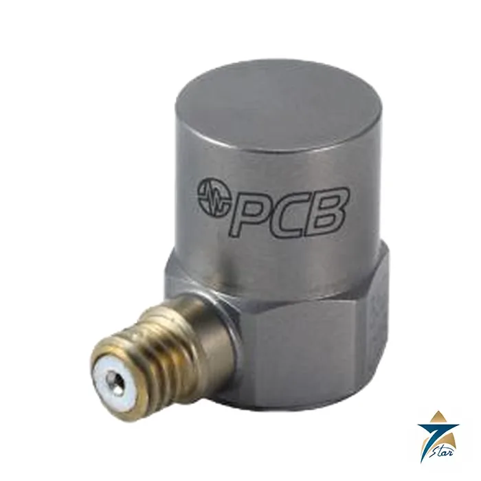
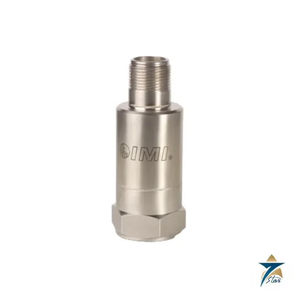
The PCB Piezotronics 352C03 is a general purpose ICP accelerometer with a ceramic shear element in a hermetically sealed titanium housing. Its 10 mV/g sensitivity and +/-500 g peak range suit higher-level vibration, structural and test applications where a 100 mV/g industrial sensor would saturate.
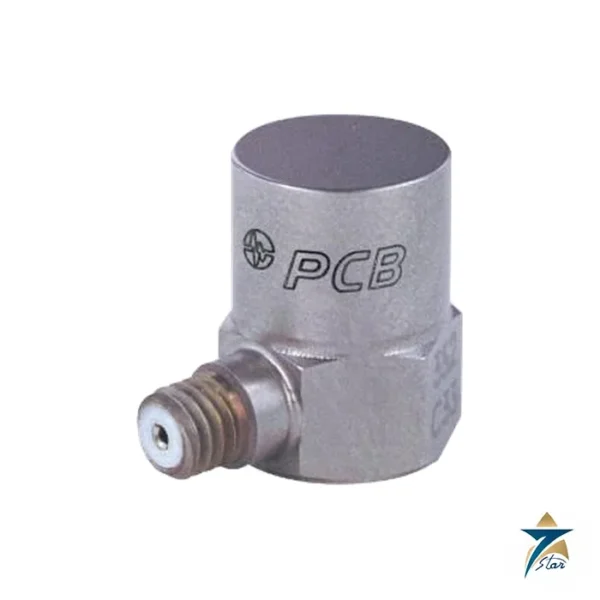
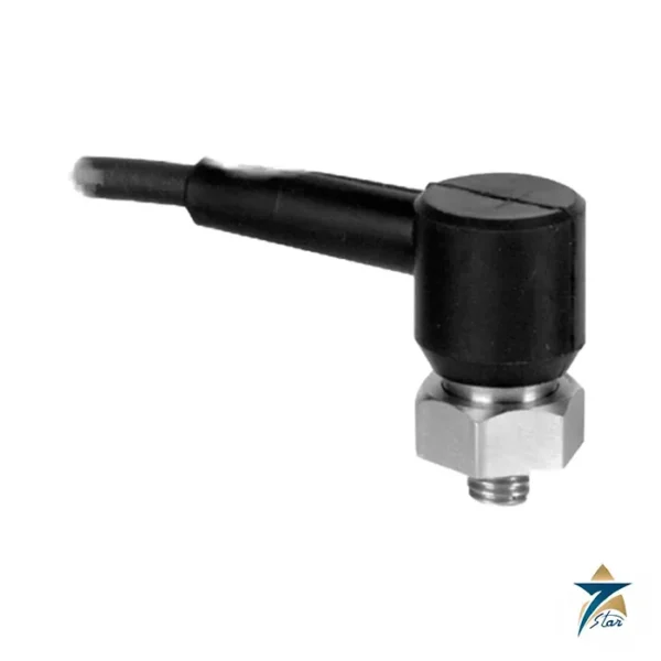
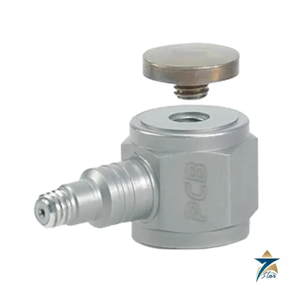
It is only 0.44 in across the hex and 0.62 in high and weighs 5.8 g, so it can be fitted on small structures without changing their dynamics much. A 10-32 coaxial jack on the side takes a standard cable, and the 10-32 female mounting thread accepts the supplied stud, adhesive base or wax.
Technical specifications
| Parameter |
Specification |
| Sensitivity (+/-10 %) |
10 mV/g (1.02 mV per m/s2) |
| Measurement range |
+/-500 g pk (+/-4,900 m/s2) |
| Frequency range (+/-5 %) |
0.5 to 10,000 Hz |
| Frequency range (+/-10 %) |
0.3 to 15,000 Hz |
| Resonant frequency |
50 kHz or more |
| Broadband resolution (1 to 10,000 Hz) |
0.0005 g rms (0.005 m/s2 rms) |
| Non-linearity / transverse sensitivity |
1 % or less / 5 % or less |
| Overload limit (shock) |
+/-5,000 g pk |
| Temperature range |
-65 to +250 F (-54 to +121 C) |
| Base strain sensitivity |
0.003 g per microstrain |
| Excitation voltage / constant current |
18 to 30 VDC / 2 to 20 mA |
| Output impedance / bias voltage |
100 ohm or less / 7 to 12 VDC |
| Discharge time constant / settling time |
1.0 to 2.5 s / under 10 s |
| Spectral noise at 1 / 10 / 100 / 1,000 Hz |
110 / 25 / 8 / 4 ug per root Hz |
| Sensing element / geometry |
Ceramic / shear |
| Housing / sealing |
Titanium / hermetic |
| Size (hex x height) |
0.44 in x 0.62 in (11.2 mm x 15.7 mm) |
| Weight |
0.20 oz (5.8 g) |
| Connector / position |
10-32 coaxial jack / side |
| Mounting thread / torque |
10-32 female / 10 to 20 in-lb (113 to 226 N-cm) |
| Supplied accessories |
Model 080A adhesive mounting base, 080A109 petro wax, 681B05 mounting stud (10-32 to 10-32), M081B05 metric stud, ACS-1 frequency response calibration |
Powering, options and mounting guidance
The sheet lists HT (high temperature, operating to 325 F or 163 C with a 22 to 30 VDC supply), J (ground isolated, with a lower 9 kHz 5 percent range), T and TLA, TLB, TLC, TLD (TEDS versions compliant with IEEE 1451.4) and W (water resistant sealed integral cable). A change of option changes some of the numbers above, so quote the full model.
The manual compares stud, adhesive, magnetic and base mounting. Stud mounting gives the best high frequency response, while adhesive mounts reduce it. The sensor should sit on a smooth flat surface with a coupling film, and a torque wrench avoids damaging the thread.
For the same 10 mV/g class in the catalogue, compare the PCB Piezotronics 352C33.
As with all ICP sensors, the 352C03 needs a constant current source of 2 to 20 mA at 18 to 30 VDC. The current-regulating diode or constant-current circuit of the signal conditioner has a very high dynamic resistance, which keeps the gain near unity, and a coupling capacitor removes the DC bias voltage so the signal is drift-free in AC mode.
What to confirm before ordering
Send the exact part number with suffix, the cable and connector style needed, the expected peak g level, temperature and whether TEDS is required.
How the PCB Piezotronics 352C03 works
Inside the housing a ceramic element is loaded by a small mass in shear. When the sensor vibrates, the mass pushes on the ceramic and the ceramic makes an electric charge in proportion to the acceleration. Built-in electronics turn this charge into a voltage signal that can travel over a normal coaxial cable. The electronics are powered by a constant current of 2 to 20 mA from a sensor supply, which is the ICP principle. The output rides on a bias voltage of 7 to 12 VDC, and the readout removes this level.
Where the 352C03 is used
- Structural and modal testing of small parts
- Vibration tests on shakers
- Shock measurements up to 5,000 g
- Machine vibration with higher levels than a 100 mV/g sensor can handle
- Electronics and aerospace component testing
Selection checklist for the 352C03
- Expected peak acceleration, within the range of 500 g
- Frequency band, 0.5 to 10,000 Hz within 5 percent
- Size and weight of the test object, with the sensor weighing 5.8 g
- Cable connection, 10-32 coaxial jack at the side
- Mounting method: stud, adhesive base or wax
- Temperature up to 250 degrees F, or the HT option for 325 degrees F
- TEDS option for automatic identification
- Ground isolation or water resistance options
Installation, commissioning and maintenance notes
Clean the surface and use the supplied stud for the best high-frequency response. Tighten the sensor to 10 to 20 in-lb. For temporary tests, use the adhesive base or petro wax, knowing that these reduce the usable frequency range. Fix the cable close to the sensor with tape so that cable motion does not add noise. Check the bias voltage at the sensor before testing, and recalibrate at the interval set by the quality system.
Requesting a quotation for the PCB 352C03
Please send the range, the option letters, the mounting accessories and the quantity. Seven Star LLC serves industrial customers in Oman and the GCC and replies with a quotation based on the information provided.
352C03 noise and resolution
The broadband resolution is 0.0005 g rms from 1 to 10,000 Hz. Spectral noise is 110 micro-g per root Hz at 1 Hz and 4 micro-g per root Hz at 1,000 Hz.
352C03 accuracy
Sensitivity is 10 mV/g within 10 percent. Non-linearity is 1 percent or less and transverse sensitivity is 5 percent or less.
352C03 supplied accessories
The sensor comes with the 080A adhesive base, 080A109 petro wax, a 681B05 mounting stud and an M081B05 metric stud. A frequency response calibration is included.
352C03 housing
The housing is hermetically sealed titanium. It is 11.2 mm across the hex and 15.7 mm high.
Sensor records for 352C03
Keep the serial number, the sensitivity from the certificate and the calibration date with the test file.
Documents and quotation
The PCB installation and operating manual for 352C03 is attached; its specification sheet is Rev E. Seven Star LLC is an independent supplier in Muscat. Further sensors: Vibration Monitoring.






Reviews
There are no reviews yet.