- Automation & ControlView all 2,239 products
- Automation Accessories
- AC Drives
- PLC & I/O Cards
- Industrial Communications
- Vibration Monitoring
- Controllers & Data Acquisition
- Isolator & Barrier
- CCTV & Security
- Safety Switches & Guard Locking
- Encoders
- Motor Soft Starters
- HMI Displays
- Pneumatic Cylinders
- Industrial Computers
- Servo Drives
- Machine Vision
- Automation Software
- Robotics



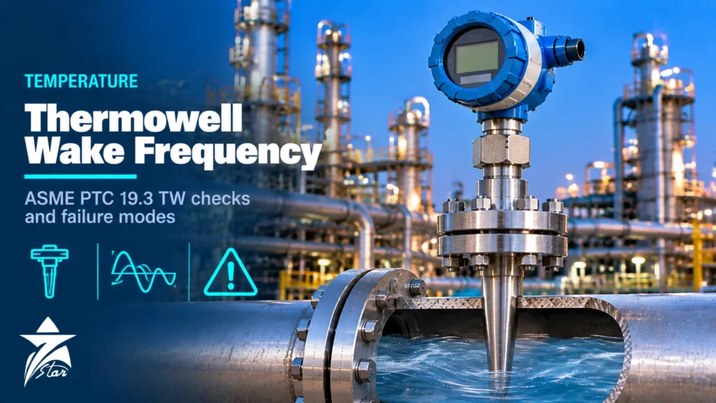
A thermowell wake frequency calculation is the check that stops a thermowell from vibrating itself to failure. Every thermowell in a flowing stream sheds vortices, and if the shedding frequency approaches the well’s natural frequency, the resulting resonance can crack the stem at its root within hours or days. The failure is sudden, the broken stem travels downstream, and the opening can release process fluid. ASME PTC 19.3 TW is the standard most projects use to evaluate this risk. This article explains the physics, what the standard actually checks, what changed in the 2016 edition, how wells fail, which design inputs you must supply, and how to fix a design that does not pass.
Why Thermowells Vibrate
When fluid flows past a cylinder, vortices form alternately on each side and detach, creating the familiar Kármán vortex street. Each detachment produces a periodic force on the cylinder. The same physics makes a vortex flow meter work; in a thermowell it is the cause of fatigue.
Two forces act on the well:
- Transverse (lift) force, perpendicular to the flow, oscillating at the vortex shedding frequency fs.
- In-line (drag) force, parallel to the flow, with an oscillating component at twice the shedding frequency, superimposed on the steady drag.
The shedding frequency is calculated from fs = St × V / d, where V is the fluid velocity, d the local diameter of the well (usually the tip diameter for the governing case) and St the Strouhal number. For circular cylinders St is roughly 0.2 over a wide Reynolds number range, and PTC 19.3 TW gives Reynolds-dependent values for use in the calculation.
Because the in-line force oscillates at 2fs, in-line resonance occurs when the shedding frequency reaches about half the natural frequency, well before transverse resonance at fs equal to the natural frequency. In-line resonance produces smaller amplitudes than transverse resonance, but it is reached at lower velocities, which is why it receives so much attention in the current standard.
The History: From the 1974 Method to TW-2010 and TW-2016
Older thermowell designs were checked against a 1974 ASME method that considered only transverse vibration and used a fixed Strouhal number. Thermowell failures, including the widely cited 1995 sodium leak at the Monju fast breeder reactor in Japan, showed that this approach was not conservative enough. ASME PTC 19.3 TW-2010 introduced a full rework: Reynolds-dependent Strouhal numbers, in-line resonance, mounting compliance, and explicit dynamic and static stress checks against material fatigue limits.
The 2016 revision kept the overall method and refined several points. It set out conditions under which a well may operate at or pass through in-line resonance, essentially limited to gas service, outside continuous operation, with an acceptable fatigue evaluation, and with the plant owner accepting responsibility. It also addressed installations in elbows and introduced a minimum tip thickness, widely quoted as 3 mm. Any calculation still based on the 1974 method, or on informal “length rules”, should be repeated to the current edition.
What PTC 19.3 TW Checks
A compliant evaluation is not a single frequency ratio. It is a sequence of checks, all of which must pass at every relevant operating condition.
| Check | What is evaluated | Typical cause of failure |
|---|---|---|
| Natural frequency | Installed natural frequency, corrected for fluid added mass, sensor mass and mounting compliance | Long unsupported length, slim root, flexible mounting |
| Frequency limit | Ratio of shedding frequency to installed natural frequency against the allowed limit | High velocity, small tip diameter |
| Dynamic stress | Oscillating bending stress at the root and at step or taper points against the material fatigue limit | Operation near resonance, high density fluids |
| Static stress | Steady drag bending plus pressure stresses against allowable stress | High velocity in dense fluids |
| Pressure rating | External pressure capacity of the shank and tip | Thin walls at high pressure, high temperature |
The frequency limit depends on the fluid. A key parameter is the Scruton number, a mass-damping parameter that combines the well’s damping with the ratio of its mass to the fluid density. For liquids, which have low Scruton numbers, in-line resonance is not suppressed and the allowed frequency ratio is typically about 0.4. For low-density gases with a Scruton number above about 2.5, in-line resonance is suppressed and a ratio up to about 0.8 may be accepted, provided the stress checks pass. Always confirm the applicable limit in the current edition of the standard rather than relying on these typical values.
Natural Frequency and Mounting Compliance
The natural frequency of an ideal cantilever depends on its unsupported length, stiffness (modulus of elasticity and cross-section) and mass per unit length. Length dominates: natural frequency falls roughly with the square of unsupported length, so a modest reduction in length gives a large frequency gain.
PTC 19.3 TW then applies corrections:
- Fluid added mass, which lowers the frequency, especially in dense liquids.
- Sensor mass inside the bore.
- Mounting compliance, because real flanges, threads and nozzles are not perfectly rigid supports.
- Elastic modulus at operating temperature, which falls as temperature rises.
The unsupported length is measured from the effective support plane. For a flanged well inside a standpipe nozzle, the portion of the stem inside the nozzle is unsupported, so tall nozzles significantly reduce natural frequency. This is a frequent cause of designs that look short on paper but fail the calculation.
A Simple Illustration
Consider a tapered well with a 19 mm tip in steam flowing at 30 m/s. Taking St as 0.22 for illustration, fs = 0.22 × 30 / 0.019 ≈ 347 Hz. If the installed natural frequency is 600 Hz, the frequency ratio is about 0.58. That would exceed a typical liquid-service limit of about 0.4, but for a low-density gas with a high Scruton number it may be acceptable, subject to the dynamic and static stress checks. The same well in a liquid line at that velocity would need redesign. The numbers here are illustrative only; real calculations must use the standard’s equations and the well’s actual geometry.
Failure Modes
Understanding how wells fail helps when reviewing a calculation or a damaged part.
- Root fatigue cracking: the classic failure. Maximum bending stress occurs at the support plane, and cracks start at the root fillet or weld.
- Step or taper transition cracking: on step-shank wells, the step is a stress raiser and must be checked separately.
- Tip loss: the separated stem travels downstream into pumps, compressors, turbines or control valves.
- Loss of containment: once the well breaks, the bore becomes an open path from the process to the sensor head.
- Erosion and corrosion thinning: wall loss reduces stiffness and pressure capacity over time, so a corrosion allowance should be considered.
- Static overstress: in very dense or very fast flows, steady drag alone can bend or overstress a long, slim well.
Typical warning signs before failure include noisy or spiky temperature readings and sensors that repeatedly fail from vibration.
Design Inputs for a Thermowell Wake Frequency Calculation
A calculation is only as good as its inputs. Most incorrect results come from using normal flow instead of maximum flow, or ignoring the nozzle.
- Fluid type (liquid, gas, steam, two-phase) and identity.
- Maximum, normal and minimum flow rate, plus pipe inside diameter, or velocities directly; include start-up, blowdown and steam-blowing cases.
- Fluid density and dynamic viscosity at each condition.
- Operating and design pressure and temperature.
- Thermowell material and profile (straight, tapered, stepped), root and tip diameters, bore diameter.
- Insertion length, unsupported length, connection type (flanged, threaded, socket weld, weld-in) and nozzle height.
- Corrosion allowance and any sour service or chloride requirements.
Fixing a Design That Fails the Thermowell Wake Frequency Calculation
When a well does not pass, change the geometry in this order of effectiveness:
- Shorten the unsupported length. This is usually the most effective change, and a shorter well usually still measures well in turbulent flow.
- Increase the root diameter or move to a tapered profile, which raises stiffness without adding as much tip diameter.
- Reduce the nozzle height or move the connection so less stem sits inside the nozzle.
- Change the material only if it changes the fatigue class or elastic modulus enough to matter.
- Consider manufacturer-specific anti-vibration designs, such as helical strakes, only where the supplier can document performance, since such features are outside the standard’s scope.
Velocity collars, sleeves and coatings are also outside the scope of PTC 19.3 TW. Collars depend on a tight, permanent fit in the nozzle, which is difficult to achieve and inspect, so most owners avoid them.
Measurement Accuracy Versus Insertion Length
Engineers often resist shortening a well because they fear conduction error. In turbulent liquid and steam flow, heat transfer to the well is high and a shorter well normally gives an accurate reading. Low-velocity gas is the main exception, where stem conduction can produce a measurable error; there the trade-off should be evaluated rather than assumed. The sensor side of this choice, including sheath diameter and spring loading, is covered in our RTD vs thermocouple guide.
GCC Applications Where It Matters Most
High-velocity gas lines in gas processing plants and compressor stations, steam headers in power and thermal desalination plants, and large crude export lines are the applications where wake frequency calculations in Oman and the GCC most often fail with standard well lengths. Sour gas service also limits material choice, which affects fatigue class and allowable stress, and seawater or brine lines may require duplex or nickel alloys that have different mechanical properties from 316 stainless steel.
Thermowell Review Checklist
- Calculation performed to ASME PTC 19.3 TW-2016 (or the edition specified by the project), not to the 1974 method.
- Maximum velocity case included, including start-up and blowdown.
- Nozzle height and mounting type reflected in the unsupported length.
- All five checks (natural frequency, frequency limit, dynamic stress, static stress, pressure) reported as passed.
- Material, fatigue class and corrosion allowance stated.
- Tip thickness and bore compatible with the sensor diameter.
- Calculation report attached to the datasheet and kept with the instrument records.
Thermowells We Supply
These examples cover flanged, threaded and weld-in thermowells.
| Product | Type | Where it fits |
|---|---|---|
| WIKA TW10 Flanged Thermowell | Flanged thermowell | Process lines and vessels. |
| WIKA TW15 Threaded Thermowell from Solid Bar Stock | Threaded thermowell from bar stock | Smaller connections. |
| JUMO 909710 Screw-In and Weld-In Thermowells | Screw-in and weld-in thermowells | Process installations. |
| WIKA TC10-B Thermocouple for Additional Thermowell | Thermocouple for thermowell | Temperature sensing. |
Send the connection, insertion length, material and process data for the wake frequency check through our quote request form.
Sourcing Thermowells Through Seven Star LLC
Seven Star LLC supplies thermowells, temperature sensors and transmitters on request for projects and maintenance in Oman and the GCC, from manufacturers such as WIKA, Endress+Hauser, Emerson and Pyromation. We help with selection and with checking that dimensions and connections match your datasheet; availability and lead time are confirmed at quotation, and the manufacturer’s wake frequency calculation can be requested together with the offer. See our temperature instrumentation and sensors and transmitters categories.
Send us the thermowell datasheet, drawing or nameplate details with the process conditions, and we will prepare a quotation and request the manufacturer’s wake frequency calculation where needed.
Frequently asked questions
What is a thermowell wake frequency calculation?
It is a check that the frequency at which vortices shed from a thermowell stays safely away from the thermowell's natural frequency, combined with stress checks on the well. ASME PTC 19.3 TW sets the method, covering natural frequency, frequency limits, dynamic and static stress, and pressure rating. Passing the frequency check alone is not a complete evaluation.
Why do thermowells fail in service?
The most common catastrophic failure is high-cycle fatigue at the root of the well, caused by resonant vibration when vortex shedding excites a natural frequency. Each vortex produces a small force, but at resonance millions of cycles accumulate quickly and a crack grows from the support plane until the stem breaks off. The broken piece can then damage downstream equipment and the opening can leak process fluid.
What changed in ASME PTC 19.3 TW-2016?
The 2016 revision refined the treatment of in-line resonance, introducing conditions under which a well may pass through in-line resonance, mainly for gas service outside continuous operation and with a fatigue check. It also clarified installation cases such as elbows and set a minimum tip thickness. Calculations based on the older 1974 method should be redone to the current edition.
Do velocity collars fix a thermowell that fails the calculation?
Velocity collars are outside the scope of PTC 19.3 TW, and their benefit depends on a tight, permanent fit in the nozzle that is hard to guarantee in the field. The preferred fixes are shortening the unsupported length, increasing root diameter, reducing tip diameter or changing to a stiffer profile. Proprietary anti-vibration designs may be used where the manufacturer can support their performance.
What process data is needed for a wake frequency calculation?
You need the maximum and minimum flow velocity (or flow rate and pipe internal diameter), fluid density and viscosity, operating temperature and pressure, and whether the fluid is liquid, gas or steam. Geometry inputs include material, insertion and unsupported length, root and tip diameters, bore, connection type and nozzle height.
Is a longer thermowell more accurate?
Not necessarily. In turbulent liquid and steam flow, heat transfer is high and a shorter well usually gives an adequate reading, while a long well is more likely to fail the vibration check. Low-velocity gas service is the case where conduction error deserves a separate check before shortening a well.
Was this guide helpful?One click helps us write better guides for engineers.
Thank you! Glad it helped. Need this equipment for your project? Request a quotation
Thank you. We will use this to improve the guide.