Vortex Flow Meter Guide: How They Work, Where They Excel and How to Size Them for Steam, Gas and Liquids
Steam headers, plant air and nitrogen networks and fuel gas lines share a measurement problem: the fluid is clean, the temperatures can be high, nobody wants moving parts, and a DP orifice run with impulse lines is more maintenance than the measurement justifies. The vortex flow meter fits this gap well. It has no moving parts, tolerates high temperature, gives a frequency output that is inherently linear with velocity, and installs as a single flanged or wafer body. It also has hard limits at low flow, sensitivity to pipe vibration and poor behaviour in pulsating or two-phase service.
How a Vortex Meter Works
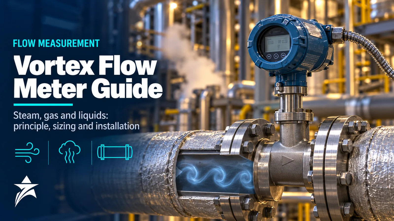
When fluid flows past a bluff body, the boundary layer separates alternately from each side and forms a regular pattern of vortices downstream, known as a Kármán vortex street. In a vortex meter the bluff body is a shedder bar spanning the bore. The shedding frequency f is related to the flow velocity v and the shedder width d by the Strouhal number:
St = f × d / v
For a well-designed shedder, the Strouhal number is close to constant over a wide range of Reynolds numbers. Within that range the shedding frequency is directly proportional to velocity, so volumetric flow is frequency multiplied by a meter constant (K-factor) established by the manufacturer’s flow calibration. The relationship does not depend on density, viscosity or conductivity, provided the Reynolds number stays in the linear range.
Each vortex produces an alternating pressure and a small alternating force on the shedder or on a sensing element behind it. Manufacturers detect this in different ways:
- Piezoelectric sensors that respond to the alternating force or stress, used in many designs including the Rosemount 8800D, whose sensor is isolated from the process so it can be replaced without breaking the process seal.
- Capacitive sensing, used by Endress+Hauser in the DSC (differential switched capacitance) sensor of the Prowirl range.
- Other strain- or pressure-based arrangements, with digital signal processing to separate the vortex frequency from vibration and noise.
Because the output is a frequency, vortex meters can provide a pulse output as well as 4–20 mA with HART or a fieldbus.
Accuracy, Turndown and the Low-Flow Limit
Typical published accuracy for volumetric flow is roughly ±0.75 to ±1% of reading for liquids and roughly ±1 to ±1.5% of reading for gas and steam, within the linear Reynolds range. These are typical figures; confirm the exact statement for the model, size and fluid on the datasheet, and note whether it is expressed for volumetric flow or for compensated mass flow.
The lower limit is the defining constraint of vortex measurement. As velocity falls:
- The Reynolds number drops and the Strouhal number starts to drift, so the meter becomes non-linear.
- The vortex signal strength, which rises with density times velocity squared, becomes too weak to separate from noise.
- The transmitter applies a low-flow cutoff and reads zero below it.
For liquids the limit is usually set by Reynolds number and a minimum velocity in the region of a few tenths of a metre per second. For gas and steam the minimum velocity depends on density: low-pressure gas needs a higher velocity than high-pressure gas to produce a detectable signal. Upper limits are set by pressure drop, cavitation in liquids and by velocity limits in gas and steam stated by the manufacturer. Turndown is therefore fluid- and size-dependent; ratios in the range of 10:1 to 20:1 or more are commonly achievable in gas and steam, but always calculate it with the vendor’s sizing tool rather than assuming a headline figure.
Sizing: Why the Meter Is Often Smaller Than the Line
Process lines are sized for pressure drop and future capacity, not for flow measurement. A vortex meter sized to line diameter often sees velocities at minimum flow below its cutoff. The common solution is to select a meter one size, sometimes two sizes, smaller than the line, with concentric reducers or with a reducer-style meter that integrates the reduction into the body. Some manufacturers offer such reducer versions, which avoids field-fabricated reducer spools.
An illustrative case shows the logic. Saturated steam at 10 barg has a density of roughly 5.6 kg/m³. A flow range of 400 to 2,000 kg/h corresponds to about 71 to 357 m³/h actual:
| Meter size (Sch 40 bore) | Velocity at 400 kg/h | Velocity at 2,000 kg/h | Assessment |
|---|---|---|---|
| DN100 (about 102 mm) | about 2.4 m/s | about 12 m/s | Minimum flow likely near or below cutoff |
| DN80 (about 78 mm) | about 4.2 m/s | about 21 m/s | Better low-end margin; check pressure drop |
| DN50 (about 52 mm) | about 9.3 m/s | about 46 m/s | Good signal, but higher pressure loss and noise |
Figures are approximate and cutoffs are model-specific, so run the actual data through the manufacturer’s sizing program. The principle holds: choose the smallest size that keeps minimum flow above cutoff while keeping maximum velocity and permanent pressure loss acceptable.
For liquids, also check the minimum downstream pressure needed to avoid cavitation. Manufacturers give a formula of the form P downstream ≥ a × ΔP + b × Pv, where ΔP is the meter pressure loss, Pv the vapour pressure and a and b coefficients specific to the design. Cavitation produces erratic high readings and can damage the shedder, so this check matters on hot water, condensate and light hydrocarbon service.
Steam Mass Flow and Multivariable Meters
A vortex meter measures actual volumetric flow. For steam, energy and mass are what matter, so density must be known. There are three common approaches:
- Saturated steam with integrated temperature: in saturated steam, density is a function of temperature alone, so a meter with an integrated temperature sensor can compute mass flow internally. The ABB VortexMaster FSV430 and the higher-function VortexMaster FSV450 are available with an integrated temperature sensor for this purpose, and the Endress+Hauser Prowirl 200 family also has versions with integrated temperature measurement.
- Superheated steam and gases: density depends on both pressure and temperature, so a pressure input is needed, either from an external transmitter read by the meter or by compensation in a flow computer or the DCS.
- External compensation in a flow computer, which is preferred where the measurement feeds energy accounting or contractual billing and where an audit trail is required.
Wet steam is the most common source of error. Water droplets do not shed vortices like vapour, and a saturated-steam density calculation assumes dry steam. The result is an error roughly related to the dryness fraction, plus noisy signals and erosion of the shedder. Install a separator and trap upstream of steam meters on long or poorly insulated lines, and avoid locating the meter immediately after a desuperheater.
Vortex Compared With Other Technologies
| Technology | Strengths | Limitations | Typical fit |
|---|---|---|---|
| Vortex | No moving parts, high temperature capability, linear frequency output, single body | Low-flow cutoff, vibration sensitivity, not for pulsating or two-phase flow, straight run needed | Steam, plant air, nitrogen, fuel gas, clean liquids |
| DP orifice | Standardised to ISO 5167, no flow calibration needed, any size | Square-root turndown about 3:1 to 4:1 per transmitter, impulse lines, permanent pressure loss | Large lines, fiscal gas with AGA 3, steam where standards are mandated |
| Coriolis | Direct mass and density, high accuracy, no straight run | Cost and weight in large sizes, pressure drop, limited in low-pressure gas | Liquids, custody transfer, dense gases |
| Ultrasonic (inline) | No obstruction, wide turndown, multipath versions for fiscal gas | Cost, sensitivity to flow profile and deposits in some designs | Large gas lines, custody transfer |
| Thermal mass | Direct mass flow for gases, very low velocity capability | Calibrated for a specific gas composition, moisture sensitivity | Compressed air, nitrogen, flare and low-pressure gas |
For a wider comparison across all technologies, see our flow meter selection guide.
Installation Requirements That Decide Accuracy
Vortex meters need a developed, swirl-free velocity profile. Straight-run requirements depend on the upstream disturbance and the manufacturer, but typical guidance is in the range of about 10D to 20D upstream after a reducer or single bend, more after two bends in different planes, and substantially more after a control valve. Downstream, about 5D is typical. Flow conditioners can shorten these lengths where the manufacturer has qualified them.
Other points that cause field problems:
- Place control valves downstream of the meter wherever possible. A throttling valve upstream generates disturbance and noise.
- Locate pressure and temperature taps for external compensation downstream of the meter, at the distances given in the manual, so they do not disturb the profile.
- Centre wafer-style meters carefully and make sure gaskets do not protrude into the bore.
- Avoid locations with strong pipe vibration, such as directly on pump discharge spools. Support the pipe on both sides of the meter. Vibration at frequencies near the vortex frequency can produce a reading at zero flow, which is one reason the low-flow cutoff is adjustable.
- On liquids, mount so the meter is always full. On steam and condensing gases, mount in horizontal lines with the electronics positioned as the manual recommends to keep condensate away from the sensor.
- Do not use vortex meters on reciprocating compressor discharge or other strongly pulsating flows. Pulsation interacts with vortex shedding and produces errors that are hard to detect.
Applications in Oman
Refineries, power and water plants and gas processing facilities in Oman use vortex meters mainly on utility services: steam distribution and boiler feed headers, plant and instrument air, nitrogen, and natural gas to fired heaters and gas turbines. Site conditions affect selection in specific ways:
- Solar gain on pipe-mounted electronics can push housing temperatures well above the 45 to 50 °C ambient. Consider a remote-mount transmitter on hot steam lines and fit sunshades.
- On long, partially insulated steam lines, condensate and wet steam are common after outages. Separators, traps and good insulation improve measurement more than meter selection does.
- In coastal plants in Sohar, Duqm and Salalah, specify housing coatings and stainless fittings suitable for saline humidity.
- For desert sites, use cable glands and housing seals that keep out fine dust, and close unused entries with certified plugs.
Common Mistakes
- Sizing to line diameter and discovering that normal winter or turndown flow sits below cutoff.
- Ignoring the cavitation check on hot water and light hydrocarbons.
- Using a saturated-steam calculation on superheated steam, or on steam downstream of a pressure reducing station.
- Raising the low-flow cutoff to hide vibration-induced readings instead of fixing the pipe support.
- Installing immediately after a control valve or a pair of out-of-plane elbows.
- Replacing an older meter, such as an Endress+Hauser Prowirl 72F, with a new model without checking face-to-face length, bore and K-factor configuration.
Vortex Flow Meter Selection Checklist
- Fluid, phase and composition, including any liquid content in gas or steam.
- Minimum, normal and maximum flow, with pressure and temperature at each.
- Required output: volumetric, compensated mass or energy, and where the compensation is done.
- Meter size from vendor sizing, with velocity at minimum flow above cutoff.
- Pressure loss at maximum flow and, for liquids, the cavitation check.
- Available straight run upstream and downstream, and need for a flow conditioner.
- Body style: wafer, flanged, reducer type, and flange rating.
- Materials, including NACE MR0175/ISO 15156 requirements for sour gas.
- Integral or remote electronics, considering temperature and vibration.
- Output protocol: 4–20 mA HART, pulse, fieldbus.
- Hazardous area certification matching the area classification.
- Calibration certificate and K-factor documentation for the records.
Sourcing Vortex Flow Meters Through Seven Star LLC
Seven Star LLC supplies vortex meters from several manufacturers, including the ABB VortexMaster range, Rosemount 8800 series meters and Yokogawa models such as the Yokogawa VY vortex flowmeter and the Yokogawa VF701. We also source replacement units for installed legacy meters from Endress+Hauser and others. Browse our flowmeters category or the ABB and Yokogawa brand pages, and send your process data so we can propose suitable options.
Share your process data sheet with Seven Star LLC and we will help you source a vortex meter sized correctly for your service.
Need a Quotation for Your Project?
- Genuine OEM products
- Supply across Oman & the GCC
- Formal quotation from our sales team
Free, no-obligation quotation · takes about 1 minute
Other enquiries: [email protected] · WhatsApp
More Blog