
- Vibration Monitoring
- Industrial Communications
- PLC & I/O Cards
- Automation Accessories
- Controllers & Data Acquisition
- AC Drives
- Industrial Computers
- Encoders
- Safety Switches & Guard Locking
- Isolator & Barrier
- Automation Software
- HMI Displays
- CCTV & Security
- Motor Soft Starters
- Servo Drives
- Robotics
- Pneumatic Cylinders
- Machine Vision
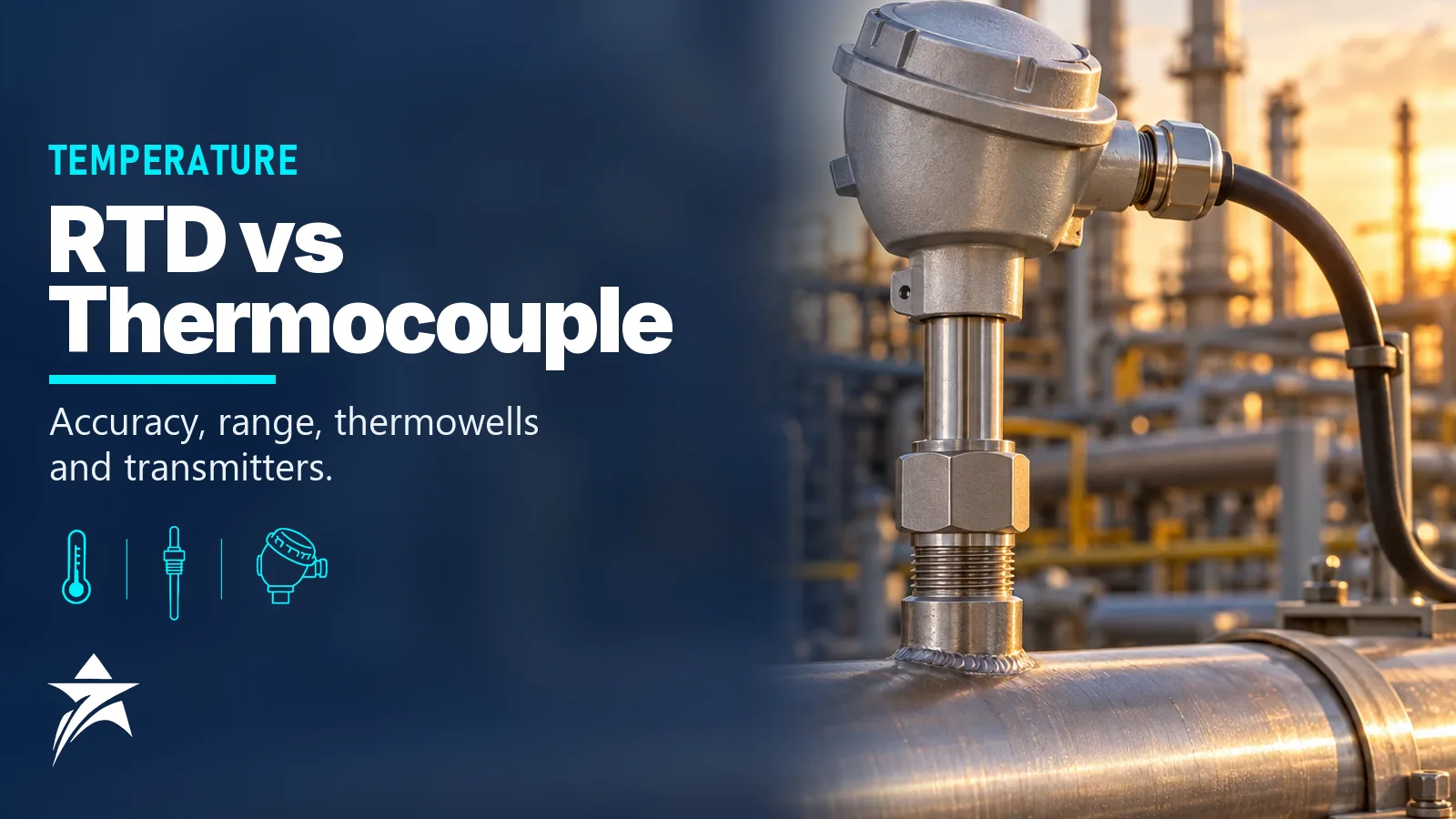
RTD vs Thermocouple: Choosing Industrial Temperature Sensors, Thermowells and Transmitters
Temperature is the most frequently measured variable in most process plants, and also one of the most frequently mis-specified. The RTD vs thermocouple decision sets the achievable accuracy, the long-term drift, the wiring cost and the behaviour under vibration, yet many datasheets simply copy the previous project. A sound choice also covers the thermowell, which is the part that fails mechanically, and the transmitter, which decides how errors from cable runs, heat and sensor ageing reach the control system.
This guide compares the two sensor families against the relevant IEC standards, then covers thermowells, transmitters and the site conditions that matter in Oman.
How RTDs Work
A resistance temperature detector measures the change in resistance of a platinum element. The industrial standard is the Pt100: 100 Ω at 0 °C, about 138.5 Ω at 100 °C, with a mean coefficient of 0.00385 Ω/Ω/°C, as defined in IEC 60751. A Pt1000 has ten times the resistance and is less sensitive to lead resistance, but Pt100 remains the default for process plants.
IEC 60751 defines tolerance classes. The validity range depends on whether the element is wire-wound or thin-film, so confirm it on the sensor datasheet. In the table, abs t is the magnitude of the measured temperature in °C.
| IEC 60751 class | Tolerance | Value at 100 °C | Typical validity, wire-wound | Typical validity, thin-film |
|---|---|---|---|---|
| AA | ±(0.10 + 0.0017·abs t) °C | ±0.27 °C | −50 to +250 °C | 0 to +150 °C |
| A | ±(0.15 + 0.002·abs t) °C | ±0.35 °C | −100 to +450 °C | −30 to +300 °C |
| B | ±(0.30 + 0.005·abs t) °C | ±0.80 °C | −196 to +600 °C | −50 to +500 °C |
| C | ±(0.60 + 0.01·abs t) °C | ±1.60 °C | −196 to +600 °C | −50 to +600 °C |
Lead wire configuration
In a 2-wire connection, lead resistance adds directly to the reading. Two 10 m conductors of 0.5 mm² copper add roughly 0.7 Ω, which a Pt100 reports as about 1.8 °C too high. A 3-wire connection compensates if the three leads have equal resistance, and is the common industrial choice. A 4-wire connection eliminates lead resistance and is preferred for custody transfer, calibration references and long runs to the input card.
Thin-film vs wire-wound
Thin-film elements are a platinum track on a ceramic substrate: robust under vibration, fast and cheaper. Wire-wound elements offer better stability and wider ranges at higher accuracy classes but are more sensitive to shock. Industrial RTDs are generally limited to about 600 °C, with many standard assemblies rated lower.
How Thermocouples Work
A thermocouple produces a voltage, the Seebeck effect, proportional to the temperature difference between the measuring junction and the reference (cold) junction. The instrument measures the cold junction temperature, usually at its terminals, and adds the equivalent voltage: cold junction compensation. Any error in that measurement goes straight into the reading, which is why a terminal block exposed to sun or a draught causes erratic values.
Thermocouple types and reference tables are defined in IEC 60584-1. For type K and type N, tolerance class 1 is ±1.5 °C or ±0.004·abs t, and class 2 is ±2.5 °C or ±0.0075·abs t, whichever is greater.
| Type | Conductors | Typical range | Notes |
|---|---|---|---|
| K | Nickel-chromium / nickel-aluminium | About −200 to +1,200 °C | General purpose, about 41 µV/°C; drift from short-range ordering at 250–600 °C and green rot in reducing atmospheres |
| N | Nicrosil / Nisil | Up to about +1,200 °C | More stable than K at high temperature; good replacement where K drifts |
| J | Iron / copper-nickel | About 0 to +750 °C | Iron leg oxidises; mostly found in older plants |
| T | Copper / copper-nickel | About −200 to +350 °C | Low temperature and cryogenic duties |
| R, S | Platinum-rhodium / platinum | Up to about +1,600 °C | Furnaces and reformers; sensitive to contamination |
| B | Platinum-30% rhodium / platinum-6% rhodium | Up to about +1,700 °C | Very low output below about 50 °C |
Extension and compensating cable
Extension cable uses the same alloys as the thermocouple. Compensating cable uses cheaper alloys that match the thermocouple’s output only over a limited temperature range. Either way, the cable type must match the thermocouple type, and polarity must be correct. A reversed pair produces an error of roughly twice the temperature difference between the head and the cold junction. Colour codes differ between IEC 60584-3 and ANSI: in the ANSI system the negative leg is always red, which surprises engineers used to red as positive.
RTD vs Thermocouple: Direct Comparison
| Attribute | RTD (Pt100) | Thermocouple (type K or N) |
|---|---|---|
| Typical accuracy | Class A: ±0.35 °C at 100 °C | Class 1: ±1.5 °C or 0.4% of reading |
| Long-term stability | Very good below about 400 °C | Drift at high temperature; type N better than K |
| Upper range | About 600 °C | About 1,200 °C (base metal), higher for noble metal |
| Vibration resistance | Good for thin-film; wire-wound more fragile | Very good, especially mineral-insulated |
| Response time | Slower; element has length and mass | Fast, small grounded junction |
| Signal | Resistance, needs excitation | Millivolts, needs cold junction compensation |
| Wiring | Ordinary copper, 3 or 4 wires | Matching extension or compensating cable |
| Typical uses | Process control below 400 °C, custody transfer, bearings | Furnaces, heaters, flue gas, reactors, exhaust |
The practical rule: use an RTD wherever the temperature allows, because it is more accurate and stable. Use a thermocouple above about 400–600 °C, for very fast response, or where severe vibration would damage an RTD element.
Thermowells: The Part That Fails Mechanically
A thermowell lets the sensor be removed without opening the process. Barstock thermowells, machined from solid bar, are stronger than fabricated wells made from tube with a welded tip and are standard for pressurised hydrocarbon service.
In high-velocity gas and steam lines, fluid shedding vortices from the thermowell can excite it at its natural frequency until it fails by fatigue. ASME PTC 19.3 TW-2016 is the current method for checking this. It evaluates the natural frequency against the vortex shedding frequency, including in-line resonance, plus steady-state and dynamic stress and pressure rating. Run the calculation for every thermowell in gas, steam and high-velocity liquid service, across the full flow range including start-up. Fixes include a shorter immersion, a thicker root, a tapered or stepped profile, or, from some manufacturers, vortex-suppressing designs; check that the calculation method covers them.
Immersion length is a trade-off. Too short and heat conduction along the well biases the reading toward ambient; a common rule of thumb is at least ten times the tip diameter. Too long and the wake-frequency margin shrinks. In small lines, install in an elbow or at an angle.
A thermowell also adds lag: the time constant is often tens of seconds. Use spring-loaded inserts so the sensor tip touches the bottom of the bore, and match bore and sensor diameters.
Transmitters: Head-Mount, Field-Mount, Multipoint and Wireless
Converting the signal near the sensor removes most lead-resistance and noise problems. Head-mount transmitters sit in the connection head; field-mount units have their own dual-compartment housing and display and are easier to service.
Useful transmitter features for critical loops:
- Dual-sensor inputs with sensor drift alert, which compares two elements and flags divergence.
- Hot backup, which switches to the second sensor if the first fails.
- Sensor-transmitter matching with Callendar-Van Dusen constants from a calibrated RTD, which can reduce system error well below the class tolerance.
- SIL capability for safety instrumented functions, confirmed by a certificate and safety manual.
- WirelessHART for monitoring points where cabling is expensive.
- Multi-input transmitters for tank farms, bearings and heater tube skins.
The Rosemount 3144P offers dual-sensor input with hot backup and drift alert. The Moore Industries STZ is built for functional safety duties, while the PR electronics 5335D is a compact HART head-mount transmitter. Field-mount options include the ABB TTF300 and Endress+Hauser TMT162. For high point counts, the Rosemount 848T handles multiple inputs on one device, and the Rosemount 648 is a WirelessHART option.
Calibrate the loop end to end, with the sensor in a dry block or bath, rather than the transmitter alone. Our instrument calibration program guide covers intervals and records.
Oman Site Considerations
- Heat on housings: in 45–50 °C ambient with direct sun, transmitter housings can run far above air temperature. Check the electronics ambient rating and the display limit, since LCDs may darken at high temperature, and fit sunshades on exposed transmitters.
- Cold junction gradients: thermocouples terminated in sun-exposed junction boxes see errors as the box heats unevenly through the day. Convert to 4–20 mA at the head instead.
- Long cable runs: millivolt and resistance signals over hundreds of metres pick up noise and lead-resistance error. A head-mount or field-mount transmitter is cheaper than the troubleshooting.
- Coastal humidity: moisture entering through a failed gland can reach mineral-insulated sheaths and reduce insulation resistance, shunting an RTD and making it read low. Use correctly rated glands and check insulation resistance during maintenance.
- Sand and erosion: thermowells in produced fluids with sand need erosion allowance or hard-facing.
Common Mistakes
- Running a 2-wire RTD to the control room and accepting a fixed offset.
- Using type K extension cable on a type N thermocouple, or mixing colour codes.
- Installing a thermowell in gas service without a PTC 19.3 TW-2016 calculation.
- Grounded thermocouple junctions on inputs that are not isolated, creating ground loops.
- Specifying class A tolerance and then using a thin-film element above its class A validity range.
- Replacing a sensor without updating the transmitter’s sensor type or matching constants.
Selection Checklist
- Normal, maximum and design temperatures; required accuracy and response time.
- Sensor type: Pt100 class and wiring, or thermocouple type and tolerance class.
- Single or dual element; insulation and sheath material (316L, Inconel for high temperature).
- Thermowell: barstock or fabricated, material, process connection, immersion and bore.
- Wake-frequency calculation to ASME PTC 19.3 TW-2016 for velocity-sensitive services.
- Transmitter: head or field mount, HART or fieldbus, dual input, SIL, display, ambient rating.
- Hazardous area certification matching the zone, gas group and temperature class.
- Cable glands and entries suited to coastal and dusty sites.
- Calibration certificate requirements and sensor-transmitter matching.
Sourcing Temperature Instruments Through Seven Star LLC
Seven Star LLC supplies and sources sensors, thermowell assemblies and transmitters across major brands. Sensor assemblies include the Rosemount 214C, Endress+Hauser TR10 and WIKA TR10 families, alongside the transmitters above. Browse the full temperature category and send the tag data so element, wiring, thermowell and transmitter can be matched.
Share your temperature instrument datasheets with Seven Star LLC and we will source matched sensors, thermowells and transmitters for your loops.
Was this guide helpful?One click helps us write better guides for engineers.
Thank you! Glad it helped. Need this equipment for your project? Request a quotation
Thank you. We will use this to improve the guide.
Need a Quotation for Your Project?
Seven Star LLC supplies the industrial equipment covered in this article to customers across Oman and the GCC. Send us the part numbers, models or a short description with quantities, and our sales team will reply with a formal quotation.
- Genuine OEM products
- Supply across Oman & the GCC
- Formal quotation from our sales team
Free, no-obligation quotation · takes about 1 minute
Other enquiries: [email protected] · WhatsApp
More Blog





Frequently Asked Questions
An RTD is more accurate and more stable in the range where both can be used. A class A Pt100 is within ±0.35 °C at 100 °C, while a class 1 type K thermocouple is within ±1.5 °C or 0.4% of reading. Thermocouples are chosen for higher temperatures, faster response or severe vibration rather than accuracy.
Industrial Pt100 sensors are generally used up to about 600 °C, and many standard assemblies are rated lower. The IEC 60751 tolerance class only applies within a validity range that depends on the element construction. Check the sensor datasheet for both the operating limit and the class validity range.
In a 2-wire RTD the lead resistance adds to the element resistance and appears as a temperature error, often more than 1 °C over typical cable lengths. A 3-wire connection compensates for lead resistance when the leads are equal, and a 4-wire connection eliminates it. Most process installations use 3-wire or 4-wire.
Extension cable uses the same alloys as the thermocouple itself, while compensating cable uses different, cheaper alloys that match the thermocouple output only over a limited temperature range. Both must match the thermocouple type and be connected with the correct polarity. Using the wrong type introduces an error at every junction.
Type K thermocouples drift because of short-range ordering in the nickel-chromium leg, typically between about 250 and 600 °C, and preferential oxidation of chromium, called green rot, in low-oxygen atmospheres at high temperature. Type N was developed to be more stable and is a common replacement where type K drift is a problem.
A wake-frequency calculation to ASME PTC 19.3 TW-2016 should be done for thermowells in gas, steam and high-velocity liquid service, where vortex shedding can excite the well into fatigue failure. Many operators require it for every thermowell. The calculation also checks static stress, dynamic stress and pressure rating.