- Automation & ControlView all 2,120 products
- AC Drives
- Automation Accessories
- PLC & I/O Cards
- Industrial Communications
- Vibration Monitoring
- Controllers & Data Acquisition
- Isolator & Barrier
- CCTV & Security
- Safety Switches & Guard Locking
- Encoders
- HMI Displays
- Pneumatic Cylinders
- Motor Soft Starters
- Industrial Computers
- Servo Drives
- Machine Vision
- Automation Software
- Robotics

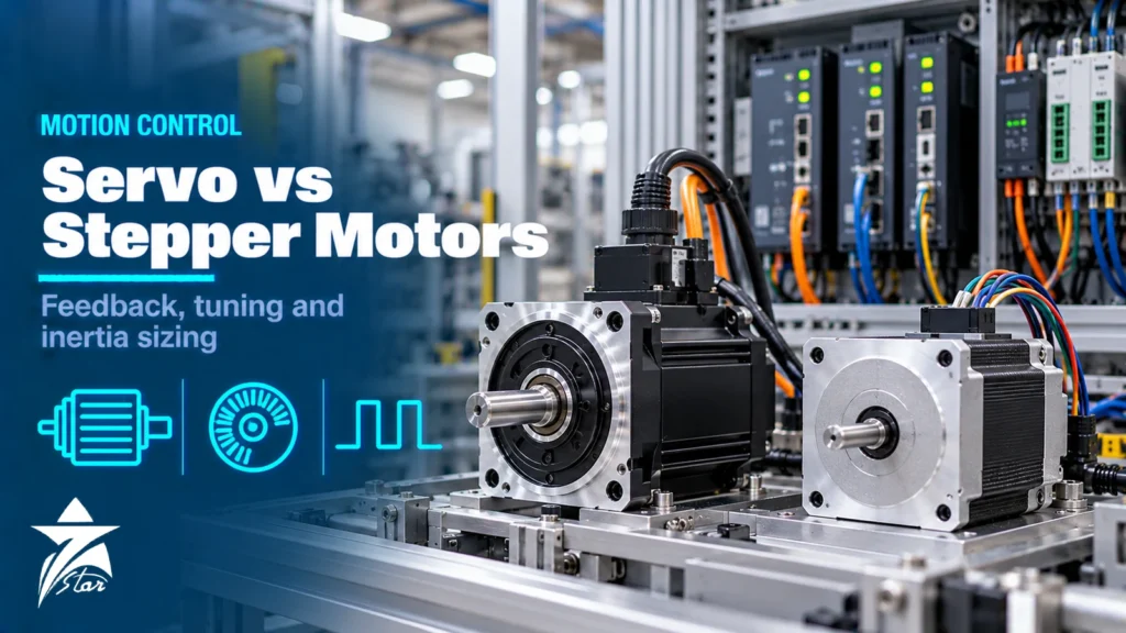
Motion control covers any axis that must move to a position, follow a speed profile or hold a torque with precision: feeders, indexing tables, cut-to-length lines, packaging machines, valve test rigs and robotic cells. The first decision on such an axis is usually servo vs stepper, followed by how to size the motor, which feedback device to use and how to tune the drive. This guide explains how servo drives and stepper systems work, compares them on torque, speed, accuracy and cost behaviour, and covers the practical engineering steps: sizing torque and inertia, choosing feedback, tuning the control loops and avoiding the mistakes that make a new axis noisy, slow or unstable.
The Building Blocks of a Motion Axis
- Motion controller: generates the trajectory (position, velocity and acceleration over time). It may be a PLC with motion functions, a dedicated motion controller or the drive itself.
- Drive (amplifier): converts supply power into controlled motor current based on commands from the controller.
- Motor: a permanent-magnet servo motor, a stepper motor or, for larger axes, an induction motor with vector control.
- Feedback: encoder or resolver measuring motor shaft position, and sometimes a second encoder on the load.
- Mechanics: gearbox, belt, ball screw, rack and pinion or direct coupling that converts motor motion into load motion.
- Network: pulse/direction, analog ±10 V, or a real-time fieldbus such as EtherCAT, PROFINET IRT, EtherNet/IP with CIP Motion, or SERCOS.
How a Servo Drive Works
A servo system is closed loop. The drive runs three nested control loops. The innermost current loop controls motor current, and therefore torque, at a very high update rate. Around it, the velocity loop compares commanded and measured speed and sets the current command. The outer position loop compares commanded and measured position and sets the velocity command. Because the drive always knows where the shaft is, it corrects disturbances immediately and can deliver short bursts of peak torque, often in the region of two to three times continuous torque for a limited time, to accelerate a load quickly.
Modern servo drives add feed-forward terms that anticipate the torque needed from the trajectory, notch filters to suppress mechanical resonances, auto-tuning routines and integrated safety functions such as Safe Torque Off (STO) defined in IEC 61800-5-2. Our servo drives section lists typical industrial drive families.
How a Stepper System Works
A stepper motor moves in fixed angular increments when its windings are energised in sequence. The common hybrid stepper has 200 full steps per revolution (1.8° per step), and the drive subdivides each step electrically through microstepping for smoother motion. A standard stepper runs open loop: the controller counts pulses and assumes the motor followed them. If the load torque exceeds what the motor can produce at that speed, the motor loses steps and the controller does not know it. Stepper torque is highest at standstill and falls substantially as speed increases.
Closed-loop or hybrid steppers add an encoder so the drive can detect and correct position errors and adjust current to the load. They sit between classic steppers and servos in performance and cost behaviour.
Servo vs Stepper: Comparison
| Characteristic | Stepper (open loop) | Servo |
|---|---|---|
| Control | Open loop, position assumed from pulse count | Closed loop with continuous feedback |
| Torque vs speed | High at low speed, falls steeply as speed rises | Roughly constant continuous torque up to rated speed |
| Peak torque reserve | Little; overload leads to lost steps | Short-term peak typically well above continuous rating |
| Typical speed range | Best at low to moderate speeds | Suits high speeds and fast acceleration |
| Position holding | Holds at standstill with full current, heats when idle | Holds actively using feedback; current follows load |
| Behaviour on overload | Stalls or loses position silently | Following-error fault reported to the controller |
| Tuning | Little or none | Required; auto-tuning helps |
| Noise and resonance | Mid-speed resonance possible; microstepping reduces it | Smooth; mechanical resonances handled with filters |
| Relative cost and complexity | Lower for small axes | Higher, justified by dynamics and reliability |
Servo vs Stepper: How to Choose
Steppers are a good fit for small, low-speed axes with predictable loads where an occasional position error is tolerable or can be checked by a sensor: adjustment axes, small dispensers, labelling heads, simple indexers. Servos are the better choice when the axis needs high speed or acceleration, carries a varying or uncertain load, must report a fault when it cannot follow the command, or runs continuously at high duty. For any axis where a lost position would damage product or machinery, closed-loop feedback is strongly preferred.
Sizing a Servo Axis
Undersized servos fault on overload; oversized ones waste money and can be harder to tune. A structured sizing method avoids both. Most manufacturers provide sizing software, but the inputs are the same.
- Define the motion profile: distance, time, maximum speed, acceleration and deceleration times, dwell, and cycles per minute.
- Calculate load inertia of all moving parts, reflected to the motor shaft through the transmission.
- Calculate torques for each segment: acceleration torque (total inertia × angular acceleration), plus friction, gravity on vertical axes, and process forces such as cutting or pressing.
- Check peak torque against the motor and drive peak ratings, at the speed where it occurs.
- Check RMS torque over the whole cycle against the motor’s continuous torque, because heating depends on the root-mean-square value, not the peak.
- Check speed against the motor’s rated and maximum speed, and confirm the drive’s supply voltage supports it.
- Add margin for uncertainty in friction and efficiency; typical engineering practice is to leave a safety factor on both peak and RMS torque.
Inertia Ratio and Why It Matters
The load-to-motor inertia ratio is the reflected load inertia divided by the motor rotor inertia. A high ratio makes the axis harder to control: the motor has to accelerate a mass much larger than itself through a coupling or belt that is never perfectly stiff, which leads to overshoot, ringing and long settling times. A common rule of thumb in sizing guidelines is to keep the ratio at about 10:1 or less, with lower ratios for highly dynamic, precise axes. Stiff, direct-coupled mechanics and modern drives with advanced tuning can tolerate higher ratios, so treat 10:1 as a starting point rather than a hard limit.
A gearbox is the usual tool for reducing the ratio: reflected load inertia falls with the square of the gear ratio, so a 5:1 reduction lowers it to one twenty-fifth. The trade-off is a lower maximum load speed and the backlash and compliance of the gearbox itself. Choosing a motor variant with higher rotor inertia is another option.
Feedback Devices
| Device | Key features | Typical use |
|---|---|---|
| Incremental encoder | Pulse output; position lost on power-down, homing needed | General servo and stepper feedback, cost-sensitive axes |
| Absolute single-turn encoder | Knows position within one revolution at power-up | Rotary axes and indexing |
| Absolute multi-turn encoder | Counts revolutions without homing, battery or gear-based | Linear axes where homing is undesirable |
| Resolver | Analog, no electronics in the motor, tolerant of heat and vibration | Harsh environments, high temperatures |
| Sin/cos and digital serial encoders | High resolution via interfaces such as EnDat, BiSS or HIPERFACE DSL | High-precision and high-dynamic axes |
The drive must support the motor’s encoder interface, so motor and drive are usually selected as a matched pair. Replacement encoders must match the original protocol and mechanical fit exactly, and absolute encoders usually need their position offset re-established after replacement.
Tuning the Control Loops
- Run the drive’s auto-tuning first with the real mechanics attached; tuning with an uncoupled motor gives meaningless results.
- Tune from the inside out: current loop (usually fixed by the drive), then velocity loop, then position loop.
- Increase velocity loop gain until the response is fast without audible noise or oscillation, then back off for margin.
- Use the drive’s frequency-response or FFT tool to identify mechanical resonances and set notch filters on them.
- Add velocity and acceleration feed-forward to reduce following error without raising feedback gains.
- Verify with trace recordings of commanded vs actual position, following error and current under real production cycles.
Installation and Environmental Points
Use the manufacturer’s shielded motor and feedback cables with correct 360° shield termination, keep feedback cables separated from power cables, and respect maximum cable lengths. Servo drives dissipate heat and need cabinet cooling sized for the summer ambient in GCC plants, where internal panel temperatures can climb well above standard 40 to 45 °C drive ratings without air conditioning. Fine dust and high humidity affect encoders and connectors, so specify motor protection ratings such as IP65 or IP67 where needed. Vertical axes need a motor holding brake and a mechanical safety concept so the load cannot fall when power or STO is applied.
Common Motion Control Mistakes
- Sizing on peak torque only and overheating the motor because RMS torque was never checked.
- Ignoring inertia ratio and spending days fighting oscillation that a gearbox would have solved.
- Using a stepper on an axis with variable load and no position check, leading to silent position loss.
- Mixing third-party motors and drives without confirming encoder protocol and motor parameter support.
- Poor cable shielding and grounding, causing encoder errors and random faults.
- Forgetting the brake and safe stopping concept on vertical or gravity-loaded axes.
Motion Axis Specification Checklist
- Motion profile: stroke, speed, acceleration, dwell and cycle rate
- Load mass or inertia, transmission type and ratio
- Process forces, friction and orientation (horizontal or vertical)
- Required positioning accuracy and repeatability
- Feedback type and need for absolute position at power-up
- Controller and network: pulse/direction, analog or real-time Ethernet
- Safety functions required: STO, safe stop, safe speed, brake control
- Supply voltage, ambient temperature, IP rating and cable lengths
- Existing motor and drive part numbers if replacing
Motion Control Products We Supply
These examples cover servo drives and feedback.
| Product | Type | Where it fits |
|---|---|---|
| Schneider Electric Lexium 32 Servo Drive | Servo drive | Machine axes. |
| Mitsubishi MR-JE-A General-Purpose Servo Amplifier | General-purpose servo amplifier | Positioning on machines. |
| Mitsubishi MR-J5-G CC-Link IE TSN Servo Amplifier | Networked servo amplifier | Synchronised axes. |
| Lenze i950-C7.5/400-3 Cabinet Servo Inverter | Servo inverter | Cabinet-mounted servo systems. |
| SICK EFS50-2KF0A023A Motor Feedback | Motor feedback encoder | Servo motor feedback. |
Send the motor torque, speed, positioning accuracy and control network through our quote request form.
Sourcing Servo Drives and Motion Components Through Seven Star LLC
Seven Star LLC supplies servo drives, servo motors, stepper systems, encoders and motion-capable PLC modules on request, together with the industrial network hardware that connects them, from manufacturers such as Siemens, Rockwell Automation, Yaskawa, Mitsubishi Electric, Bosch Rexroth and Beckhoff. We can help with selection and cross-checking part numbers for matched motor and drive pairs. Availability and lead time are confirmed at quotation.
Replacing a servo drive or motor, or sizing a new axis? Send Seven Star LLC the nameplates of the drive and motor, the encoder type or your RFQ, and we will quote a matched solution.
Frequently asked questions
What is the main difference between a servo and a stepper motor?
A servo system is closed loop: the drive continuously measures position with an encoder or resolver and corrects errors. A standard stepper is open loop and assumes the motor followed each pulse, so it can lose steps without detection if the load is too high. Servos also keep useful torque at high speed, while stepper torque falls steeply as speed rises.
What load-to-motor inertia ratio should a servo axis have?
A common rule of thumb is about 10:1 or less, with lower ratios for highly dynamic or precise axes. Stiff mechanics and modern drives with advanced tuning can tolerate higher ratios, so the figure is a guideline. A gearbox reduces reflected inertia by the square of the gear ratio.
Why is RMS torque important in servo sizing?
Motor heating depends on the root-mean-square torque over the whole motion cycle, not the peak. A motor can meet peak torque during acceleration yet overheat if the RMS torque exceeds its continuous rating. Both peak and RMS values must be checked with margin.
Resolver or encoder for a servo motor?
Resolvers are analog devices without electronics in the motor, so they tolerate high temperature, shock and vibration well. Digital encoders offer much higher resolution and absolute multi-turn position through interfaces such as EnDat, BiSS or HIPERFACE DSL. The drive must support whichever device the motor uses.
What is Safe Torque Off (STO)?
STO is a drive safety function defined in IEC 61800-5-2 that removes the energy that produces torque in the motor without opening the main power circuit. It prevents unexpected movement but does not hold a load, so vertical axes still need a brake and a safe mechanical concept.
Are closed-loop steppers a good alternative to servos?
For small and medium axes they often are. They add an encoder to a stepper so the drive can detect and correct position errors and reduce heating, giving better reliability than open-loop steppers at a lower cost than many servo systems. For very high speed, high dynamic or high power axes, a servo is still usually the better choice.
Was this guide helpful?One click helps us write better guides for engineers.
Thank you! Glad it helped. Need this equipment for your project? Request a quotation
Thank you. We will use this to improve the guide.