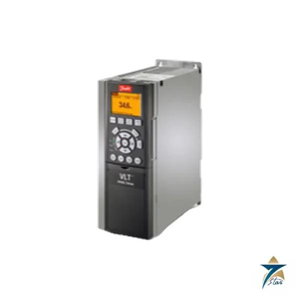
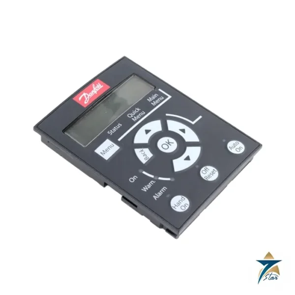
A 2.2 kW FC 302 with graphical control panel and RFI filter for fast commissioning
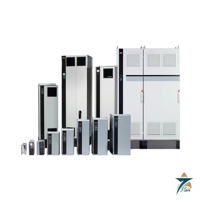
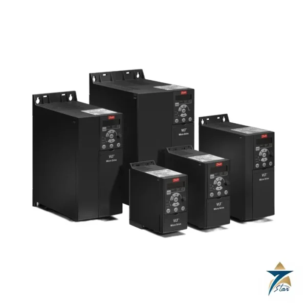
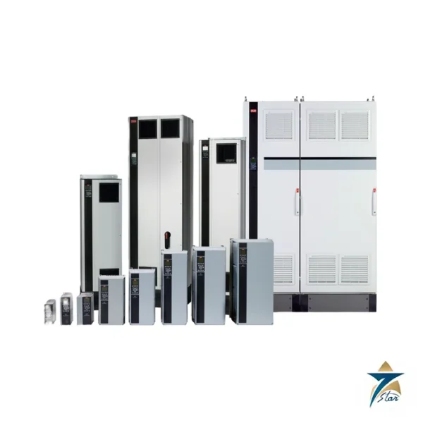
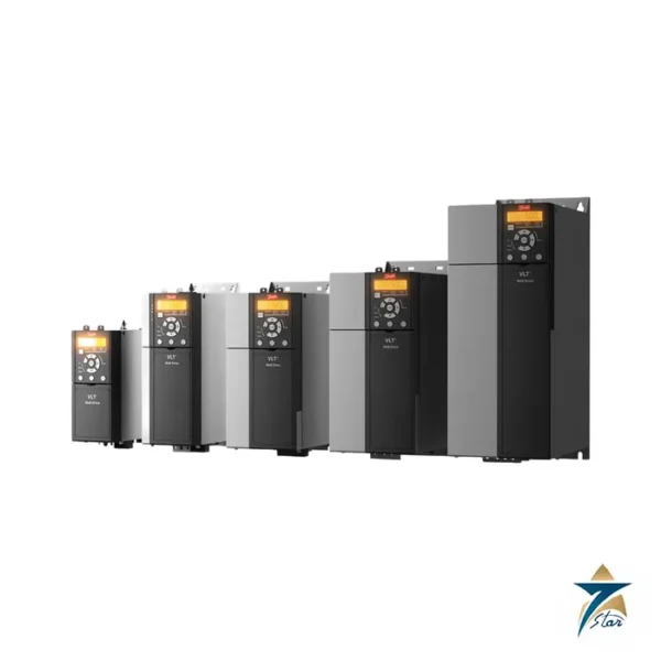
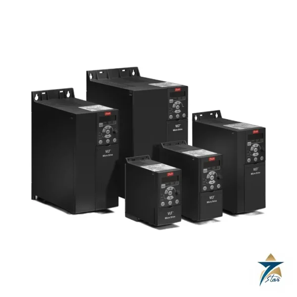
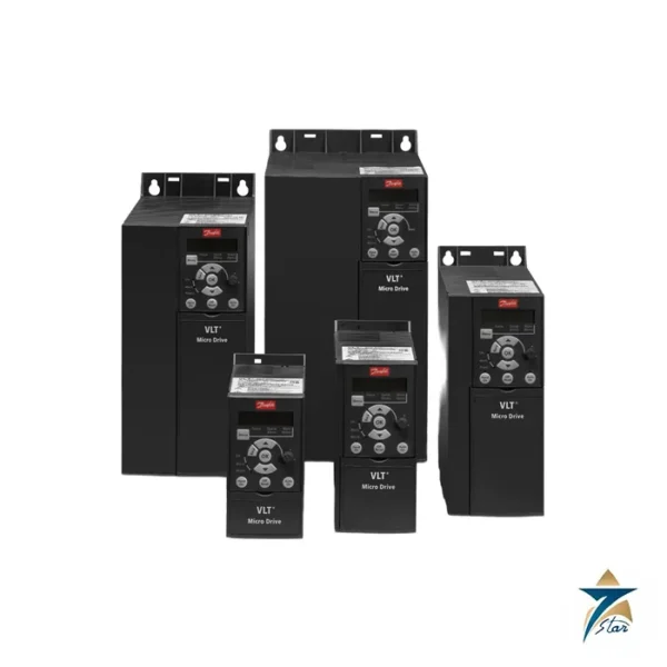
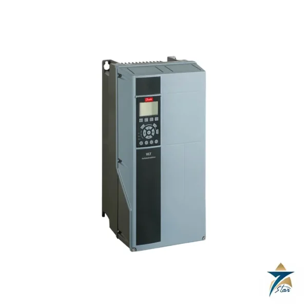
Danfoss order number 131B0148 identifies the VLT AutomationDrive type FC-302P2K2T5E20H2XGCXXXSXXXXAXBXCXXXXDX. It is the 2.2 kW (3 hp) FC 302 in frame A2, delivered with a graphical local control panel (type-code letter G), an integrated RFI filter and conformal-coated electronics, with no fieldbus or functional options installed. The FC 302 is the higher-performance sibling of the FC 301: it adds a second relay, six digital inputs, encoder and pulse inputs and control modes that range up to servo-like applications, which is why a small 2.2 kW unit is often chosen for positioning axes and precise process drives as well as for ordinary pumps and fans.
Technical specifications
| Parameter |
Specification |
| Order number / type code |
131B0148 / FC-302P2K2T5E20H2XGCXXXSXXXXAXBXCXXXXDX |
| Typical shaft output, high overload |
2.2 kW (3 hp), 160% torque for 60 s |
| Supply |
3 x 380-500 V AC +/-10%, 47.5-63 Hz |
| Output current 380-440 V |
5.6 A continuous, 9.0 A intermittent |
| Output current 441-500 V |
4.8 A continuous, 7.7 A intermittent |
| Apparent power |
3.9 kVA at 400 V; 3.8 kVA at 460 V |
| Maximum input current |
5.0 A (380-440 V), 4.3 A (441-500 V) |
| Frame, enclosure |
A2, IP20 chassis |
| Dimensions H x W x D |
268 x 90 x 205 mm (220 mm deep with A/B option); 150 mm wide with two C options |
| Estimated power loss at rated load |
88 W; efficiency about 97% |
| Output frequency / ramp times |
0-590 Hz (dependent on voltage and power); 0.01-3600 s |
| Danfoss store data |
Net weight 4.04 kg, gross weight 4.886 kg, volume 21.569 l, EAN 5702427096332, ECCN US 3A999.a |
Decoding FC-302P2K2T5E20H2XGC…
| Type-code part |
Meaning |
| FC-302 |
VLT AutomationDrive FC 302 |
| P2K2 |
2.2 kW / 3 hp |
| T5 |
Three phase 380-500 V AC |
| E20 |
IP20 / chassis |
| H2 |
RFI filter |
| X |
No brake chopper |
| G |
Graphical local control panel |
| C |
Coated PCB |
| X / X / X |
No mains option, standard cable entries, no adaptation |
| AX / BX |
No A option, no B option |
| CX / DX |
No C0 or C1 option, no D option |
Control interface and selection
The FC 302 control card offers six programmable digital inputs (terminals 18, 19, 27, 29, 32, 33; PNP or NPN, 0-24 V DC, pulse range 0-110 kHz), two analog inputs configurable for voltage or 0/4-20 mA, one analog output, two relays (relay 1 is rated 240 V AC, 2 A resistive), a 24 V supply for 200 mA, RS-485 and a USB port. System response time on the digital inputs is 2 ms or better, and open-loop speed range is 1:100 of synchronous speed. Shielded motor cables up to 150 m and unshielded up to 300 m are permitted for the FC 302.
With no option cards fitted, add a fieldbus such as the PROFINET MCA 120 in the A slot or a relay or encoder card later, using the same drive. For fuse selection the operating guide recommends gG-10 for this frame and rating. The Danfoss store page also shows an “Upgrade available” notice for this code, so confirm with us whether the current revision or a successor is being supplied.
Sizing the 131B0148 against the motor and the duty
Size this drive on motor current rather than on kilowatts alone. Compare the motor nameplate current at the actual supply voltage with the continuous output current listed for the 380-440 V and 441-500 V bands, and check that the intermittent rating covers the starting or acceleration torque the machine really needs. A 2.2 kW motor with a high-inertia load, frequent reversing or a short ramp may call for the next frame size even though the power figure matches.
- Confirm the supply voltage and frequency at the panel, not just the nominal network value.
- Note whether the application needs a brake resistor; this code has no brake chopper, so regenerative loads such as fast-stopping conveyors or hoists need a different variant.
- Decide which fieldbus or encoder feedback will be used, so that the empty option slots can be filled when the drive is ordered or later.
- Check the planned motor cable length and type against the limits stated for the FC 302.
Installation and first start-up
The IP20 chassis is intended for mounting inside a cabinet. Fit the drive vertically with clear space above and below for the cooling air, as described in the operating guide, and keep heat sources such as braking resistors or transformers away from its air inlet. Use a shielded motor cable with the shield bonded at both ends with proper clamps, separate the motor cable from control and encoder wiring, and connect the protective earth before any other conductor.
On the graphical panel, enter the motor nameplate data first and run the automatic motor adaptation with the motor cold and uncoupled where possible. Then set the control mode, the speed reference source, the ramps and the function of the digital inputs. For an application using terminal 27 as coast stop, verify that the input is wired before trying to run, since an open input is a frequent cause of a drive that shows ready but will not start. Save the finished parameter set to the panel so it can be copied to a replacement drive.
Maintenance and fault finding
- Overtemperature alarms: clean the heat sink and fan path, and check the cabinet internal temperature before changing parameters.
- Overcurrent trips during acceleration: lengthen the ramp or review the motor data and adaptation results.
- Earth fault messages: test the motor and cable insulation with the drive disconnected.
- Unstable speed: check the analog reference wiring and its shield, and confirm the selected input mode matches the signal type.
Keep a log of alarm and warning codes read from the panel. Patterns in that log usually point to the cause faster than repeated resets.
Operating the FC 302 in Oman and GCC conditions
The conformal-coated electronics in this code help where cabinet air carries dust or moisture, which is common in Omani industrial areas and coastal sites. Coating is not a substitute for a good enclosure, though. In summer the cabinet interior can be far hotter than the outside air, so allow for the estimated power loss in the cabinet heat calculation and use a cooling unit or filtered fans sized for the peak season rather than an average day.
Fine dust clogs filter mats quickly, reducing airflow without any visible warning, so replace or clean filters on a fixed schedule. Near the sea, salt-laden air and condensation at night can attack terminals and connectors; keep cable glands sealed and consider anti-condensation heating in cabinets that stand idle. During long shutdowns, power the drive periodically so that the electronics stay dry.
Documents and quotation
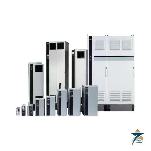
The Danfoss operating guide for enclosure sizes A-C is attached as a download. See also our Danfoss VLT AutomationDrive FC 302 page and the AC drives category. Send us the label data of the drive you are matching and please confirm the exact code with us before ordering.





Reviews
There are no reviews yet.