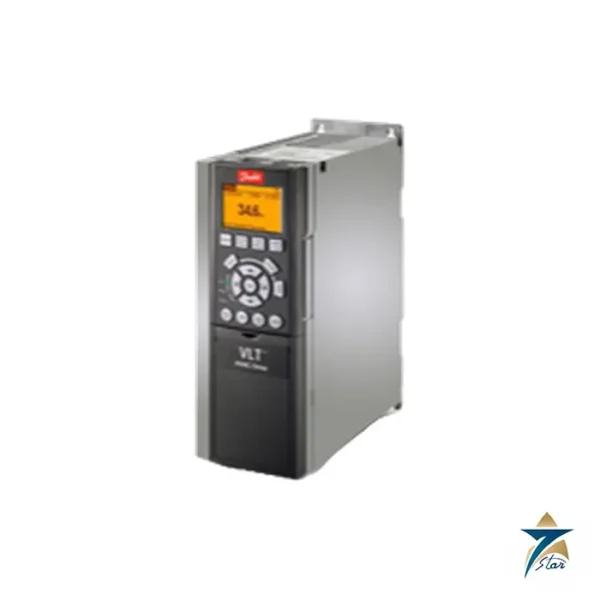
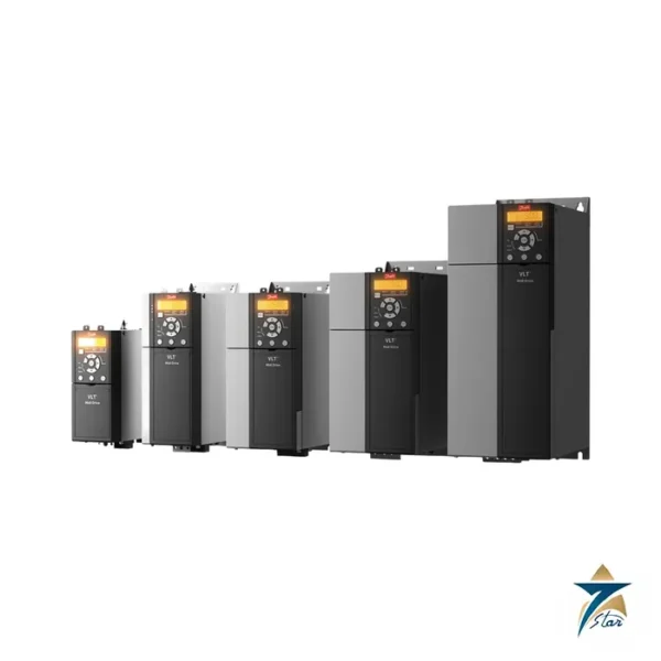
A 7.5 kW FC 302 in frame A3 with encoder feedback fitted for closed-loop speed control
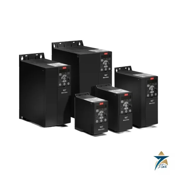
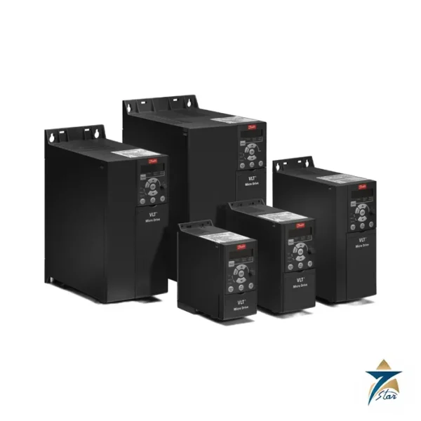
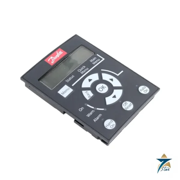
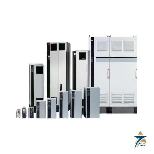
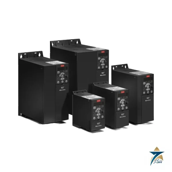
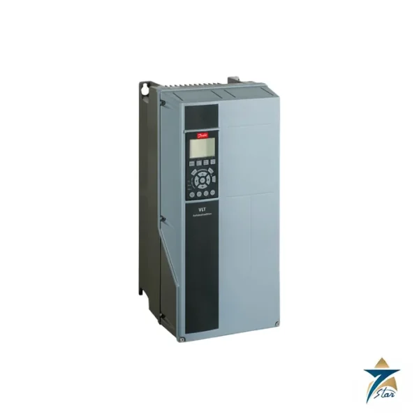
Danfoss order number 131U5502 is a configured VLT AutomationDrive, type FC-302P7K5T5E20H2XNCXXXSXXXXAXBRCXXXXDX. It combines the 7.5 kW (10 hp) power size in the wider A3 frame with a numerical local control panel (letter N), the RFI filter, coated electronics and a factory-fitted MCB 102 encoder option in the B slot (type code BR). The encoder card is what distinguishes this part from the plain 7.5 kW drive: it lets the FC 302 run closed-loop speed control with feedback from an incremental encoder on the motor shaft, which is needed for conveyors with tight speed tolerances, winders, test benches and similar precision machines.
Technical specifications
| Parameter |
Specification |
| Order number / type code |
131U5502 / FC-302P7K5T5E20H2XNCXXXSXXXXAXBRCXXXXDX |
| Shaft output, high overload |
7.5 kW (10 hp) |
| Supply |
3 x 380-500 V AC |
| Output current 380-440 V |
16 A continuous, 25.6 A intermittent |
| Output current 441-500 V |
14.5 A continuous, 23.2 A intermittent |
| Apparent power |
11 kVA at 400 V |
| Maximum input current |
14.4 A (380-440 V), 13 A (441-500 V) |
| Enclosure, frame |
IP20 chassis, A3 |
| Dimensions H x W x D |
268 x 130 x 205 mm (220 mm deep with A/B option); 190 mm wide with two C options |
| Control panel |
Numerical LCP |
| Option fitted |
B option: MCB-102 encoder option |
| Speed accuracy, closed loop |
0-6000 rpm: error +/-0.15 rpm, depending on feedback resolution |
| Danfoss store data |
Net weight 6.07 kg, gross weight 7.076 kg, volume 27.246 l, EAN 5702427969186, ECCN US 3A999.a |
Type code of 131U5502
| Type-code part |
Meaning |
| P7K5 |
7.5 kW / 10 hp |
| T5 |
380-500 V three phase |
| E20 |
IP20 chassis |
| H2 |
RFI filter |
| X |
No brake chopper |
| N |
Numerical local control panel |
| C |
Coated PCB |
| AX |
No A option |
| BR |
MCB-102 encoder option |
| CX / X / XX |
No C0 option, no C1 option, no C-option software |
| DX |
No D option |
Closed-loop control and selection
The operating guide specifies a speed control range of 1:100 of synchronous speed in open loop and 1:1000 in closed loop, with a speed accuracy of +/-8 rpm open loop and +/-0.15 rpm closed loop (the latter depending on the encoder), plus torque control accuracy within +/-5% of rated torque with speed feedback. Encoder inputs are on terminals 32 (A) and 33 (B), with a maximum frequency of 110 kHz for push-pull signals. Verify the supply voltage and the encoder type of the motor before ordering.
The recommended fuse for this A3 drive is gG-16, with a maximum of gG-32 and a Moeller PKZM0-25 breaker. Mount it with 100 mm free air above and below. The Danfoss store page also shows an “Upgrade available” notice for this code, so confirm with us whether the current revision or a successor is being supplied.
The relay outputs of this FC 302 are rated as follows in the Danfoss guide: relay 1 handles 240 V AC at 2 A, while relay 2 is rated 400 V AC at 2 A on the normally open contact 4-5 and 240 V AC on the normally closed contact 4-6. Use these values when planning brake, fault or run signalling circuits.
Connecting the motor encoder
The value of 131U5502 lies in its encoder feedback, so the encoder connection deserves the same care as the power wiring. Before installation, confirm from the motor or encoder data sheet that the device is an incremental type with A and B tracks that suits the MCB 102 input, and note its pulses per revolution and supply voltage. Use a twisted-pair, overall shielded cable, keep it separate from the motor cable along its whole route, and clamp the shield as described in the operating guide rather than leaving long pigtails.
Mechanical mounting matters as much as wiring. An encoder on a loose coupling or a bent stub shaft produces a noisy speed signal, and the drive will try to correct movements that the motor is not actually making. Check run-out and coupling condition when the motor is fitted, and protect the encoder housing against impacts from maintenance work around the machine.
Commissioning closed-loop speed control
Start by entering the motor nameplate data and running an automatic motor adaptation with the motor uncoupled where possible. Then set the encoder resolution in the feedback parameters and turn the motor slowly in open loop while watching the feedback speed on the numerical control panel. The sign and value must match the commanded direction and speed; if the reading is negative or unstable, correct the encoder channel order or the direction parameter before switching to closed loop.
Once the feedback is proven, select the closed-loop speed mode and tune the speed controller with the real load connected. Increase the proportional gain in small steps until the response is fast without audible hunting, then adjust integral time to remove steady-state error. Save the final settings to the control panel memory or a PC tool so that the configuration can be copied to a replacement unit.
Signals to the control system
Plan which relay and digital outputs report run, warning and alarm states to the PLC or DCS, and include an encoder fault alarm in that list. A clear feedback-loss response, for example a controlled stop, should be agreed with the machine designer and tested during commissioning rather than discovered later.
Panel environment and maintenance in Oman
The coated electronics on this drive help against humid and contaminated air, but the IP20 chassis still needs a suitable enclosure. In Oman, panels near the coast face salt-laden humidity, while inland plants deal with heat and fine dust. Size enclosure cooling for summer conditions, keep fan filters clean, and check that the airflow path above and below the A3 frame is not blocked by cable ducts added during later modifications.
At planned shutdowns, check torque on power terminals, inspect the encoder cable and connectors for damage, and review the alarm log for recurring feedback faults. Repeated short encoder alarms often point to shielding or grounding problems that are easier to fix before they stop production.
Documents and quotation
The manufacturer operating guide for A-C frames is attached as a download. See also the Danfoss VLT AutomationDrive FC 302 page and the AC drives category. Please send us the label data and the motor encoder specification, and confirm the exact code with us before ordering.





Reviews
There are no reviews yet.