- Automation & ControlView all 1,777 products
- AC Drives
- Industrial Communications
- PLC & I/O Cards
- Vibration Monitoring
- Automation Accessories
- Controllers & Data Acquisition
- CCTV & Security
- Safety Switches & Guard Locking
- Isolator & Barrier
- Encoders
- Industrial Computers
- Servo Drives
- HMI Displays
- Motor Soft Starters
- Pneumatic Cylinders
- Automation Software
- Machine Vision
- Robotics
















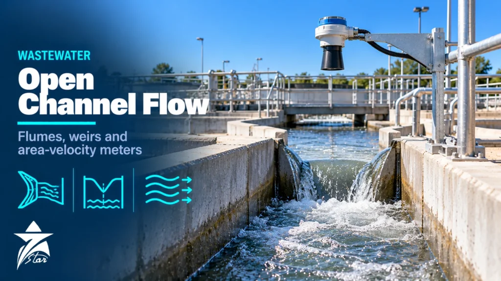
Open channel flow measurement is how most wastewater treatment plants, sewage lift stations, industrial effluent outfalls and irrigation systems measure flow, because the water runs in a partly filled channel or pipe rather than a full pressurised line. Instead of measuring velocity directly, you force the water through a device with a known relationship between depth and flow, measure the depth, and convert it to flow. When it works, it is simple and robust. When it does not, the cause is usually a level sensor in the wrong place, a submerged flume, or an approach channel that breaks the assumptions behind the rating equation. This guide covers primary devices (flumes and weirs), level sensors, level-to-flow conversion, area-velocity meters, installation rules and the checks that keep readings credible for operators and regulators.
How Level-to-Flow Measurement Works
An open channel flow system has two parts. The primary device is a flume or weir that creates a fixed, repeatable relationship between upstream depth (head) and flow rate. The secondary device is a level sensor plus a flow transmitter that measures head and applies the equation for that primary device.
The relationship is not linear. For a Parshall flume the general form is Q = C·Ha^n, where C and n depend on the throat width and n is around 1.5. For a 90° V-notch weir, flow rises with roughly the 2.5 power of head. This has two consequences:
- A small error in head becomes a larger error in flow. On a V-notch, a 1% head error gives about 2.5% flow error.
- Zero setting is critical. If the level sensor zero is a few millimetres off at low flows, the percentage error can be very large.
Accuracy therefore depends far more on the primary device being built and installed to its standard, and on careful head measurement, than on the electronics.
Parshall Flumes
The Parshall flume is the most widely used flume in municipal wastewater. It has a converging inlet section, a parallel throat with a dropped floor, and a diverging outlet. The size is designated by throat width (W), from 1 inch up to 50 feet. Standard rating equations exist for each size; the US Bureau of Reclamation Water Measurement Manual, for example, lists Q = 0.992·Ha^1.55 for a 3-inch flume and Q = 3.95·Ha^1.55 for a 1-foot flume, with Q in ft³/s and Ha in feet. ASTM D1941 and ISO 9826 cover the measurement method.
Strengths for wastewater:
- Self-cleaning: the accelerating flow carries grit and solids through, so there is no pool of settled sludge upstream.
- Low head loss compared with a weir of similar capacity.
- Wide flow range for each size.
- Prefabricated fibreglass or stainless flumes are available, which helps achieve correct dimensions.
The head Ha is measured in the converging section, typically at two-thirds of the converging wall length upstream of the throat. Everything in the rating equation assumes that location.
Submergence
If the downstream water level backs up, the flume becomes submerged and the free-flow equation over-reads. Submergence is the ratio Hb/Ha, with Hb measured near the downstream end of the throat. The free-flow transition limit depends on size: about 50% for 1–3 inch flumes, 60% for 6–9 inch, 70% for 1–8 ft and 80% for the largest sizes. Above that, you need an Hb sensor and a submerged-flow correction, and accuracy drops. The better solution is to design the downstream channel, outlet level and flume elevation so that the flume stays in free flow at all expected flows.
Other Flume Types
- Palmer-Bowlus flumes: designed to be installed inside an existing sewer pipe or manhole channel. They are compact and need little fall, which makes them common in collection systems.
- H-flumes: developed for agricultural runoff; they handle a very wide flow range including very low flows, and are used on small industrial discharges.
- Long-throated (broad-crested) flumes: rectangular, trapezoidal or U-shaped flumes covered by ISO 4359 and modern design software. They tolerate higher submergence than Parshall flumes and can be designed for a specific channel.
- Cutthroat flumes: flat-floored, without a parallel throat; easier to build but less widely standardised.
Weirs
A thin-plate weir is a sharp-edged plate across the channel. Water flows over the crest, and the head above the crest sets the flow. ISO 1438 covers rectangular and triangular (V-notch) thin-plate weirs.
- V-notch weirs (commonly 90°, also 60° and 22.5°) are very sensitive at low flows. The Kindsvater-Shen equation applies to fully contracted notches over a range of angles. For a 90° notch, a widely used metric approximation is Q ≈ 1.38·h^2.5 with Q in m³/s and h in metres.
- Rectangular weirs handle larger flows. They can be contracted (the notch is narrower than the channel) or suppressed (the crest spans the full channel width).
- Cipolletti (trapezoidal) weirs have sloping sides that simplify the equation and are common in irrigation.
Weirs are accurate in clean water and easy to verify, but they create a pool upstream where solids settle. In raw sewage this sediment changes the approach conditions and the effective crest height, and rags can catch on the crest. They are better suited to final effluent, treated water, cooling water and storm water than to raw influent.
Head must be measured upstream of the drawdown zone, at least about four times the maximum head upstream of the plate. The crest must stay sharp and clean, and the nappe must spring clear of the plate with air underneath.
Comparing Primary Devices
| Device | Best for | Solids handling | Head loss | Key limitation |
|---|---|---|---|---|
| Parshall flume | Raw and treated wastewater, plant inlet and outlet | Good | Low to moderate | Submergence must be controlled |
| Palmer-Bowlus flume | Sewer pipes, manholes | Good | Low | Narrower flow range |
| H-flume | Small discharges with wide range | Moderate | Moderate | Not ideal for heavy solids |
| V-notch weir | Low flows of clean effluent | Poor | High | Sediment upstream, needs free fall |
| Rectangular weir | Larger clean flows | Poor | High | Approach pool and aeration needs |
| Area-velocity meter | Sewers, surcharged pipes, no fall available | Good | None | Profile, sediment and fouling sensitivity |
Level Sensors for Head Measurement
The secondary device has to measure millimetres reliably over years. The usual options:
- Ultrasonic non-contact sensors: the most common choice. They need temperature compensation because sound speed changes with air temperature, a clear path free of foam and walls, and the correct blanking distance. In hot climates, direct sun on the sensor and the channel walls creates temperature gradients in the air column; a sunshade and correct mounting height reduce this.
- Radar non-contact sensors: unaffected by air temperature and less affected by light foam and wind. Increasingly used as costs have fallen. See our radar level transmitter guide for the technology background.
- Submerged pressure sensors: work where a non-contact sensor has no clear view, but they foul in raw sewage and need density and zero checks.
- Bubblers: a small air flow from a tube on the channel floor; the back pressure equals the head. Robust against foam and floating debris, but need an air supply and periodic tube cleaning.
- Stilling wells: a side well connected to the measuring point through a pipe; it calms surface turbulence and gives a protected place for a float or sensor.
The level instrumentation category covers ultrasonic, radar and hydrostatic sensors used for head measurement.
Area-Velocity and Other Alternatives
Where there is no room or fall for a flume or weir, area-velocity (AV) meters measure depth and mean velocity directly. Doppler or transit-time sensors mounted on the pipe invert, or radar velocity sensors above the surface, estimate velocity, and the cross-sectional area comes from depth and pipe geometry. They suit sewers, surcharged pipes and backwater conditions where flumes fail. Their accuracy depends on how well the measured velocity represents the mean velocity, so profile, sediment and sensor fouling need regular attention.
Slope-hydraulic methods using the Manning equation estimate flow from depth alone in a uniform pipe. They are useful for rough surveys but depend on a roughness coefficient that changes with sediment and slime, so they are not suitable for billing or compliance. For full-pipe sections downstream of a pump, an electromagnetic flowmeter is usually more accurate than any open channel method; the flowmeters category and our guide on how to choose the right flow meter cover those options.
Installation Rules That Decide Accuracy
- Provide a straight, uniform approach channel upstream with no bends, drops, gates or pump discharges close to the device, so the velocity distribution is even and the surface calm.
- Set the primary device level in both directions and at the elevation that avoids submergence at maximum flow.
- Build the device to the exact standard dimensions; small errors in throat width or crest geometry translate directly into rating errors.
- Mount the level sensor at the defined head location, square to the water surface, rigidly fixed so it cannot move during cleaning.
- Set zero carefully: for a flume, zero is the floor level of the converging section at the measuring point; for a weir, the crest elevation. Verify with a staff gauge or a calibrated scale.
- Keep the downstream channel free of obstructions that could raise tailwater.
- Provide safe access for cleaning, inspection and manual head checks.
Common Mistakes
- Mounting the ultrasonic sensor over the throat because it is convenient, rather than at the defined head point.
- Accepting a flume set too low, so it runs submerged at high flows.
- Using a weir on raw sewage and then fighting sediment in the approach pool.
- Ignoring foam and floating grease that give false echoes to ultrasonic sensors.
- Entering the wrong flume size or equation in the flow transmitter.
- Never checking zero after the channel has been cleaned or the sensor bracket has been disturbed.
Maintenance and Verification
A routine programme keeps the reading defensible:
- Clean the flume or weir and approach channel regularly; remove grease, algae and debris, especially from weir crests.
- Compare the transmitter head with a staff gauge or manual measurement at the head point, at least monthly and after any work in the channel.
- Check that the sensor bracket has not moved and the sensor face is clean.
- Review flow trends for steps or drifts that do not match pump operation or plant events.
- Periodically verify flow independently, for example with a portable area-velocity meter or by a volumetric check against a tank of known size.
- Record all checks; regulators and auditors rely on this record as much as on the flow total.
Flow data is usually combined with water quality measurements to calculate loads. The liquid analytical systems category and our article on water quality analyzers for desalination and wastewater cover the analyzers that typically sit alongside the flow measurement.
Open Channel Flow Measurement Specification Checklist
- Location: plant inlet, outlet, sewer, industrial discharge or irrigation channel
- Minimum, normal and maximum flow, and future flow growth
- Channel dimensions, available fall and downstream water levels
- Water quality: raw sewage, settled, treated effluent, solids and grease content
- Primary device type and size (Parshall, Palmer-Bowlus, H-flume, weir, or AV meter)
- Head sensor type, range, mounting height and blanking distance
- Need for submergence (Hb) measurement
- Flow transmitter functions: equation library, totaliser, logging, outputs (4–20 mA, relays, Modbus)
- Environmental conditions: sun exposure, ambient temperature, H2S, washdown
- Verification method and access for cleaning and manual checks
Open Channel Flow Products We Supply
These products cover level-based and velocity-based measurement in channels.
| Product | Type | Where it fits |
|---|---|---|
| Endress+Hauser Prosonic S FMU90 Ultrasonic Level and Flow Transmitter | Ultrasonic level and flow transmitter | Flumes and weirs with a level-to-flow curve. |
| Mobrey DMSP400 Ultrasonic Level and Flow Transmitter | Ultrasonic level and flow transmitter | Open channel flow and pump control. |
| Pulsar MicroFlow Open Channel Velocity Sensor | Open channel velocity sensor | Channels where velocity must be measured as well as level. |
| VEGA VEGAPULS 21 80 GHz Radar Level Sensor | 80 GHz radar level sensor | Non-contact level over channels and weirs. |
| Nivelco EasyTREK Ultrasonic Level Transmitter | Ultrasonic level transmitter | Simple level measurement in wastewater. |
Send the channel shape and size, the flume or weir type and the flow range through our quote request form.
Sourcing Open Channel Flow Equipment Through Seven Star LLC
Seven Star LLC supplies open channel flow transmitters, ultrasonic and radar level sensors, area-velocity meters and prefabricated flumes on request from manufacturers such as Endress+Hauser, Siemens, VEGA and other open channel specialists. We help with selection, sizing data review and cross-checking part numbers for replacement sensors and controllers; availability and lead time are confirmed at quotation.
Send us your channel drawing, flow range and existing sensor or flume details (nameplate, model code or datasheet), and we will prepare a quotation for the right open channel flow measurement equipment.
Frequently asked questions
What is the difference between a flume and a weir?
A weir is a plate or wall across the channel that the water flows over, and the head above the crest sets the flow. A flume is a shaped constriction that accelerates the water through a throat without a vertical barrier. Weirs are simple and accurate in clean water but trap solids; flumes pass solids and lose less head, which is why they are preferred for raw wastewater.
Where should the level sensor be placed on a Parshall flume?
The free-flow head Ha is measured in the converging section, at a point two-thirds of the converging wall length upstream of the throat for most sizes. Measuring anywhere else, for example at the throat or at the flume inlet, introduces systematic errors. Large flumes use a slightly different location defined in the dimension tables for that size.
What is submergence in a Parshall flume?
Submergence is the ratio of the downstream head Hb to the upstream head Ha, both measured from the crest of the converging floor. Below the transition limit, which ranges from about 50% for the smallest flumes to about 80% for the largest, the flow depends only on Ha. Above that limit, the free-flow equation over-reads and a second head measurement and correction are needed.
How far upstream of a weir should head be measured?
Head should be measured at least four times the maximum head upstream of the weir plate, where the water surface has not yet started to draw down. Measuring too close to the plate reads low because the water surface curves down toward the crest. A stilling well or a sensor over a calm section improves the reading.
Can ultrasonic level sensors be used for flume measurement?
Yes, non-contact ultrasonic sensors are the most common head sensors on flumes and weirs. They need temperature compensation, a mounting position free of foam and obstructions, and protection from direct sun, which creates temperature gradients in the air column. Radar sensors are an alternative where foam, wind or temperature effects cause problems.
When is an area-velocity flow meter better than a flume?
Area-velocity meters measure depth and velocity directly in an existing pipe or channel, so no primary device has to be built. They suit sewers, surcharged pipes and channels without enough fall for a flume or weir. They are more sensitive to velocity profile, sediment and sensor fouling, so accuracy depends heavily on site conditions.
Was this guide helpful?One click helps us write better guides for engineers.
Thank you! Glad it helped. Need this equipment for your project? Request a quotation
Thank you. We will use this to improve the guide.