- Automation & ControlView all 1,761 products
- AC Drives
- Industrial Communications
- PLC & I/O Cards
- Vibration Monitoring
- Automation Accessories
- Controllers & Data Acquisition
- CCTV & Security
- Safety Switches & Guard Locking
- Isolator & Barrier
- Encoders
- Industrial Computers
- Servo Drives
- Motor Soft Starters
- HMI Displays
- Pneumatic Cylinders
- Automation Software
- Machine Vision
- Robotics
















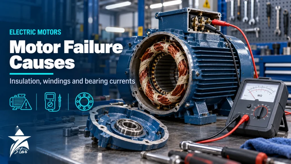
An unplanned motor failure on a critical pump or compressor can stop a process line, and the repair is often only the smaller part of the cost. Most failures, however, give warning: insulation resistance falls, winding resistances drift apart, bearings get noisier and hotter, and vibration rises. Understanding the main electric motor failure causes and knowing which condition checks reveal each one lets maintenance teams find problems early and plan repairs. This guide covers the failure statistics, insulation resistance and polarization index testing, winding tests, bearing failures including those caused by variable speed drives, and the environmental factors that matter most on hot, dusty GCC sites.
Electric Motor Failure Causes: The Survey Data
Two widely cited surveys of large induction motors give a consistent picture. An EPRI study attributed about 41% of failures to bearings, 36% to the stator, 9% to the rotor and 14% to other causes. An IEEE Industry Applications Society survey found around 44% bearing-related, 26% winding-related, 8% rotor-related and 22% other. The exact shares depend on motor size, voltage and duty, but bearings and windings together account for most failures in both.
| Component | Typical root causes | Key condition checks |
|---|---|---|
| Bearings | Poor lubrication, contamination, misalignment, overload, electrical discharge from drives | Vibration analysis, bearing temperature, ultrasound, grease condition |
| Stator winding | Thermal ageing, contamination, moisture, voltage surges, unbalance, overload | Insulation resistance, polarization index, winding resistance, surge test |
| Rotor | Broken bars or end rings from frequent starts, thermal stress | Motor current signature analysis, vibration at slip-related frequencies |
| Shaft and coupling | Misalignment, fatigue, soft foot | Alignment checks, vibration phase analysis |
| External | Supply problems, cooling blockage, driven equipment faults | Voltage and current measurement, thermography, inspection |
Thermal Ageing and Overheating
Insulation life depends strongly on temperature. A widely used rule of thumb is that insulation life roughly halves for every 10 °C of continuous operation above its rated thermal class. Causes of overheating include overload, frequent starting, high ambient temperature, blocked cooling fins or fan covers, and supply problems.
- Voltage unbalance: a small voltage unbalance causes a much larger current unbalance and extra heating; NEMA MG 1 recommends derating above 1% unbalance.
- Undervoltage and overvoltage: both increase losses at full load, and undervoltage also reduces starting torque.
- Frequent starts: each start dissipates heat in the rotor and stator; check the permitted number of starts per hour.
- Cooling: dust-packed fins and fan covers are common in desert environments and can raise winding temperature significantly.
Insulation Resistance Testing
Insulation resistance (IR) testing applies a DC voltage between the winding and the frame and measures the resulting current. It is the most common routine electrical check on motors and is described in IEEE 43, the recommended practice for testing insulation resistance of rotating machines. Test voltage depends on the winding’s rated voltage; for windings below 1000 V, 500 V DC is typical, with higher voltages for medium-voltage machines.
Readings are strongly influenced by temperature and humidity, so for trending they should be corrected to a common base, usually 40 °C. As a rough guide, insulation resistance halves for every 10 °C rise in winding temperature. IEEE 43 recommends minimum values at 40 °C, such as 5 MΩ for most random-wound windings and form-wound windings below 1 kV, and 100 MΩ for most form-wound windings above that voltage. A reading above the minimum is not proof of good insulation; a falling trend over several tests is often more important than any single value.
Polarization index
The polarization index (PI) is the ratio of the insulation resistance after 10 minutes to the reading after 1 minute. Clean, dry insulation shows an increasing reading as absorption current decays, giving a PI above 2.0 for most modern insulation classes (IEEE 43 recommends a minimum of 2.0 for class B and above). A PI near 1.0 suggests moisture or contamination. Very high IR values, above several thousand megohms, can make PI less meaningful, and IEEE 43 recognises this.
Winding Resistance and Surge Testing
Insulation resistance checks the ground wall, but not the insulation between turns, which is where many failures begin. Additional tests complete the picture:
- Winding resistance: measured phase to phase with a low-resistance ohmmeter. Unbalance beyond a few percent suggests a shorted turn, a loose connection or a wrong connection.
- Surge test: applies a fast voltage pulse to compare the waveforms of each phase; differences reveal turn-to-turn insulation weaknesses that IR testing cannot detect.
- Hipot test: applies an elevated voltage to prove the ground wall; usually reserved for acceptance or after repair because it can stress aged insulation.
- Motor current signature analysis: analyses the supply current while running to detect broken rotor bars, eccentricity and some load problems.
Suitable instruments, from insulation testers to motor analysers, are found among portable test and measurement equipment. Record test voltage, duration, winding temperature and humidity so that results can be compared over time.
Bearing Failures
Bearings are the leading cause of motor failure in most surveys. The most common root causes are related to lubrication: too little grease, too much grease, the wrong grease type, mixing incompatible greases, or contamination from dust and water entering through seals. Over-greasing is a frequent mistake that raises bearing temperature and can force grease into the winding.
- Follow the motor’s relubrication interval and quantity, adjusting for temperature and speed.
- Use the grease type stated on the motor plate and avoid mixing thickener types.
- Keep seals and grease fittings clean, especially on outdoor motors in dusty sites.
- Check shaft alignment and belt tension, since misalignment and overtightened belts overload bearings.
- Replace bearings with the correct type, clearance and seal or shield arrangement; see the ball bearings range.
Bearing Currents from Variable Speed Drives
Motors fed from PWM drives experience common-mode voltage, which can drive current through the bearings to ground. Repeated electrical discharges through the lubricant film create tiny pits and, over time, a regular washboard pattern called fluting on the bearing races, together with darkened, degraded grease. Symptoms include rising noise and vibration at bearing defect frequencies, often within a year or two of commissioning on a drive.
Guidance on bearing currents is given in IEC TS 60034-25 for converter-fed motors and in NEMA MG 1 Part 31 for definite-purpose inverter-fed motors. Common mitigation measures include:
- Insulated bearings (often on the non-drive end) or hybrid bearings with ceramic rolling elements on larger motors.
- Shaft grounding rings or brushes to give the current a low-impedance path that bypasses the bearings.
- Symmetrical shielded motor cables with proper 360° glanding and high-frequency equipotential bonding between motor and drive.
- Common-mode filters or output filters on the drive where cable lengths and voltages require them.
Vibration Monitoring
Vibration measurement detects bearing defects, misalignment, unbalance, looseness and some electrical faults. ISO 20816-3 gives evaluation zones for overall vibration velocity on industrial machines by size and foundation type. Trending overall levels catches deterioration; spectrum analysis and envelope or demodulation techniques identify bearing defects at an early stage. Online vibration monitoring sensors suit critical motors, while route-based portable checks cover the rest. The vibration monitoring system guide compares online, wireless and portable options.
Rotor Faults
Rotor failures are less frequent than bearing or winding failures but can be costly on large motors. In squirrel-cage rotors, cracked or broken bars and end rings usually result from thermal and mechanical stress during starting, so motors with heavy, high-inertia loads or many starts per hour are most exposed. Early signs include sidebands around the supply frequency in the current spectrum, spaced at twice the slip frequency, along with pulsating current and vibration under load. Motor current signature analysis can detect these without stopping the motor. Rotor eccentricity, where the air gap is uneven because of bearing wear or a bent shaft, shows up in both current and vibration spectra and can lead to rotor rubbing the stator if ignored.
Building a Condition Monitoring Routine
Tests are most useful when they are repeated under similar conditions and the results are compared. A practical routine ranks motors by criticality and assigns checks to each group.
- List motors by criticality, considering production impact, safety, redundancy and lead time for replacement.
- For critical motors, combine online vibration and temperature monitoring with periodic electrical tests at planned shutdowns.
- For important motors with spares, use monthly or quarterly route-based vibration, thermography and lubrication checks.
- For non-critical motors, rely on basic inspection and run-to-failure with a replacement plan.
- Store results in one place with dates, conditions and test settings, and review trends before each shutdown.
- After each failure, record the root cause and adjust the routine so that similar failures are caught earlier.
Environmental Electric Motor Failure Causes on GCC Sites
Heat, dust, humidity and salt air accelerate several failure mechanisms at once. Coastal plants see condensation in motors that stand idle overnight, followed by moisture in the windings. Standby pumps that do not run for weeks are particularly exposed.
- Use anti-condensation heaters on motors that stand idle in humid locations, and check that they work.
- Choose an enclosure rating suited to dust and water exposure, and keep drain plugs in place where the design calls for them.
- Shade motors from direct sun where practical and keep cooling paths clear.
- Run standby motors periodically, and test insulation resistance before starting a motor that has been idle in damp conditions.
- Inspect terminal boxes for moisture, corrosion and loose connections.
Motor Condition Check Checklist
- Insulation resistance and PI, corrected to 40 °C and trended.
- Winding resistance balance between phases.
- Supply voltage level and unbalance at the motor terminals.
- Running current per phase compared with nameplate.
- Bearing temperature, vibration and lubrication records.
- Signs of bearing current damage on drive-fed motors.
- Cooling fins, fan cover and ventilation clear.
- Heaters, terminal boxes and seals in good condition.
Condition Check Equipment We Supply
These products cover the checks described above.
| Product | Type | Where it fits |
|---|---|---|
| FLIR E54 Advanced Thermal Imaging Camera | Thermal imaging camera | Finding hot terminals, bearings and overloaded windings. |
| Fluke 87V Industrial Multimeter | Digital multimeter | Voltage balance and basic electrical checks. |
| Bently Nevada 990-05-XX-03-05 2-Wire Vibration Transmitter | 2-wire vibration transmitter | Continuous vibration monitoring on critical motors. |
| PCB Piezotronics 682C05 Bearing Fault Detector Transmitter | Bearing fault detector transmitter | Early warning of bearing damage. |
| SKF TKSA 41 Laser Shaft Alignment Tool | Laser shaft alignment tool | Removing misalignment between motor and load. |
Send the motor rating, the problem you see and the checks already done through our quote request form.
Sourcing Motors and Spare Parts Through Seven Star LLC
Seven Star LLC supplies electric motors, bearings, shaft grounding rings and test instruments on request for industrial users in Oman and the GCC. We help with selection and cross-checking part numbers, including matching replacement motors to existing nameplate data and frame sizes. Availability and lead time are confirmed at quotation.
Send us the motor nameplate photo, bearing numbers or your RFQ, and we will check the details and return an itemised quotation.
Frequently asked questions
What is the most common cause of electric motor failure?
Bearing failures are the most common cause in most surveys, accounting for roughly 40 to 45% of failures of large induction motors, followed by stator winding failures. Lubrication problems, contamination and misalignment are the main bearing root causes.
What is a good insulation resistance value for a motor?
IEEE 43 recommends minimum values corrected to 40 °C, for example 5 MΩ for most random-wound windings and form-wound windings below 1 kV, and 100 MΩ for most form-wound windings above that. Trends over time are often more meaningful than one reading.
What does the polarization index show?
The polarization index is the ratio of the 10-minute to the 1-minute insulation resistance reading. Clean, dry insulation usually gives a value of 2.0 or more. A value close to 1.0 suggests moisture or contamination in the winding.
How do VFDs damage motor bearings?
PWM drives create common-mode voltage that can discharge through the bearing lubricant film. Repeated discharges pit the races and can form a fluting pattern, leading to noise, vibration and early failure. Insulated or hybrid bearings, shaft grounding and proper cabling reduce the risk.
How does voltage unbalance affect motors?
A small voltage unbalance causes a much larger current unbalance and additional heating in the winding. NEMA MG 1 recommends derating motors when voltage unbalance exceeds 1%, and unbalance should be checked at the motor terminals when overheating is found.
How often should motor insulation be tested?
Many plants test critical motors annually or during planned shutdowns, and test any motor that has been idle in damp conditions before starting it. Online monitoring can supplement periodic tests on critical machines. The interval should reflect criticality, environment and past results.
Was this guide helpful?One click helps us write better guides for engineers.
Thank you! Glad it helped. Need this equipment for your project? Request a quotation
Thank you. We will use this to improve the guide.