- Automation & ControlView all 1,706 products
- AC Drives
- Industrial Communications
- PLC & I/O Cards
- Vibration Monitoring
- Automation Accessories
- Controllers & Data Acquisition
- CCTV & Security
- Safety Switches & Guard Locking
- Encoders
- Isolator & Barrier
- Industrial Computers
- Servo Drives
- Motor Soft Starters
- HMI Displays
- Pneumatic Cylinders
- Automation Software
- Machine Vision
- Robotics
















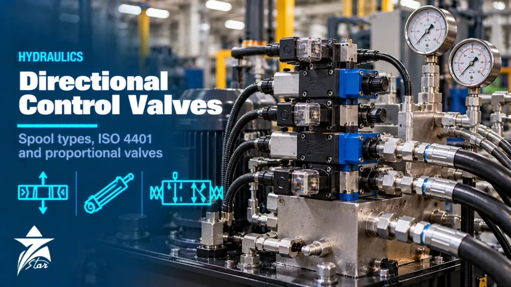
When a hydraulic cylinder drifts, a press moves too slowly or a mobile machine jerks on start, the problem is very often in the valve that steers the oil. Directional control valves decide where flow goes: which cylinder port is pressurised, which drains to tank and what happens when the valve is centred. Replacing one correctly needs more than matching the voltage on the coil. The spool type, the ISO 4401 mounting pattern, the actuation method and, for proportional and servo valves, the electronics all have to match. For maintenance teams and contractors looking for a hydraulic valves supplier in Oman, it also covers the pressure and flow control valves that work alongside them. This guide explains how directional valves work, how to read spool symbols, how the ISO 4401 interface sizes line up with NG and Dxx codes, and how to choose between on/off, proportional and servo valves.
How a Directional Control Valve Works
Most industrial directional valves are sliding-spool designs. A precision-ground spool moves inside a bore in the valve body, opening and closing passages between the ports. The standard port names are P (pressure from the pump), T (tank return), and A and B (the two service ports to the actuator). Some valves add X and Y for pilot supply and drain.
Valves are described by the number of ports and positions. A 4/3 valve has four ports and three spool positions: two working positions that drive the actuator in each direction and a centre position. A 4/2 valve has two positions only, usually with a spring return. Seat-type (poppet) directional valves are also used where zero leakage is needed for load holding, because a sliding spool always has a small internal clearance leakage.
Spool Types and Centre Conditions
The centre position defines what the circuit does when the valve is de-energised. Choosing the wrong centre is a classic replacement error: the new valve fits the subplate and the coils work, but the machine behaves differently.
| Centre condition | Port connections in centre | Typical effect |
|---|---|---|
| Closed centre | P, T, A and B all blocked | Actuator held (with some spool leakage); pump must unload via another valve or a variable pump |
| Open centre | P, T, A and B all connected | Pump unloads to tank at low pressure; actuator free to move |
| Tandem centre | P connected to T, A and B blocked | Pump unloads while actuator is held; common in mobile and simple circuits |
| Float centre | P blocked, A and B connected to T | Actuator floats freely; used with pilot-operated check valves and hydraulic motors |
| Regenerative and special spools | Varies by manufacturer code | Faster extension, soft switching or specific circuit functions |
Manufacturers use their own letters or numbers for spool symbols, so a spool code from one catalogue does not mean the same thing in another. Always compare the ISO 1219 graphical symbol on the nameplate or circuit diagram, not just the code.
ISO 4401 Mounting Patterns
ISO 4401 standardises the mounting surface (the bolt pattern and port positions) of subplate-mounted four-port directional valves. This allows valves of the same size from different manufacturers to fit the same subplate or manifold, though spool, solenoid and electrical details still differ.
| ISO 4401 size code | Common nominal size | Equivalent NFPA / CETOP designation | Typical use |
|---|---|---|---|
| 02 | NG4 | — | Very small flows, pilot stages |
| 03 | NG6 | D03 / CETOP 3 | Most common size for machine tools and small power units |
| 05 | NG10 | D05 / CETOP 5 | Presses, mobile and medium industrial circuits |
| 07 | NG16 | D07 | Larger flows, often pilot operated |
| 08 | NG25 | D08 | High-flow pilot-operated valves |
| 10 | NG32 | D10 | Very high flow, heavy presses and steel mills |
Maximum pressure and flow vary by model and manufacturer. Check the datasheet rather than assuming two valves with the same pattern have the same rating, particularly on tank port pressure, which is often lower than the P port rating.
Subplate, sandwich and cartridge construction
Subplate valves bolt onto a plate or manifold carrying the ISO 4401 pattern, so they can be replaced without disturbing pipework. Sandwich (modular) valves with the same pattern stack between the directional valve and the subplate to add functions such as pilot-operated checks, flow controls or pressure reducing valves in each line, which keeps compact power units tidy. Screw-in cartridge valves follow a different logic: they fit into machined cavities in a custom manifold, and the cavity standard, not ISO 4401, decides interchangeability. When asking for a replacement, state which construction you have, because a stack height or cavity mismatch is as much of a problem as a wrong spool.
Actuation: Solenoid, Pilot and Manual
- Direct solenoid operated: the solenoid pushes the spool directly. Common in NG6 and NG10. Simple and fast, limited in flow by the solenoid force.
- Pilot operated (solenoid-controlled pilot): a small NG6 pilot valve shifts a larger main spool hydraulically. Used for NG16 and above. Needs adequate pilot pressure, supplied internally or externally.
- Manual, mechanical and hydraulic: lever, cam roller or pilot pressure operation for mobile equipment and simple circuits.
- Coils: AC or DC voltages, wet-pin designs, connector standards such as DIN EN 175301-803 or Deutsch connectors in mobile equipment, and Ex-certified coils for hazardous areas.
For valves in classified areas, the coil certification must match the zone, gas group and temperature class; our hazardous area classification guide explains how to read those markings. The same logic applies to the pneumatic and process solenoid valves used elsewhere on site.
On/Off vs Proportional vs Servo Valves
A switching (on/off) valve has two or three spool positions and fixed flow paths. Speed is set by flow controls elsewhere in the circuit. Proportional and servo valves position the spool continuously according to an electrical command, so flow and direction are controlled smoothly.
| Feature | On/off directional | Proportional | Servo (servo-proportional) |
|---|---|---|---|
| Spool position | Discrete | Continuous, proportional to command | Continuous, closed-loop spool position |
| Spool lap | Overlapped | Usually overlapped, with dead band | Zero or near-zero lap |
| Response | Switching time only | Moderate | Fast, high frequency response |
| Electronics | Coil only | Amplifier card or onboard electronics (OBE) | Onboard or external electronics with spool feedback |
| Oil cleanliness | Standard industrial | Stricter | Strictest; fine filtration required |
| Typical use | Clamping, simple cylinders, mobile functions | Presses, injection moulding, speed and acceleration ramps | Test rigs, steel mills, turbine controls, precise positioning |
Modern high-response proportional valves with zero-lap spools and onboard electronics have narrowed the gap with classic servo valves, and many applications that once needed a flapper-nozzle servo valve now use them. The deciding factors are required frequency response, accuracy, cost and how clean the system can be kept.
Directional Control Valves: Selection Data to Collect
- Function: on/off, proportional or servo; open or closed-loop control.
- Spool type and centre condition, read from the ISO 1219 symbol.
- ISO 4401 size and mounting (subplate, manifold, sandwich stack), or cartridge cavity if not a subplate valve.
- Maximum pressure at P, A, B and T, and maximum flow.
- Actuation: direct or pilot, internal or external pilot and drain.
- Coil voltage, AC or DC, power, connector type, manual override and Ex certification if required.
- For proportional and servo valves: command signal (±10 V, 4–20 mA), feedback type, onboard or separate amplifier, and enable signals.
- Fluid type, viscosity range, temperature and seal material (NBR, FKM).
Installation and Common Mistakes
- Fitting a replacement with the right pattern but a different spool, which changes the circuit’s centre behaviour.
- Swapping internal and external pilot or drain plugs during replacement, causing the main spool not to shift or the valve to shift unexpectedly.
- Over-tightening mounting bolts unevenly, which distorts the body and makes the spool stick.
- Ignoring tank line back pressure above the valve’s T port rating.
- Running proportional valves without ramps, which causes shock loading and noise.
- Commissioning servo valves on a system that has not been flushed to the required cleanliness level.
Troubleshooting and Maintenance
Contamination is the main cause of spool sticking, slow response and internal leakage. Silt particles wedge in the clearance between spool and bore, and varnish builds up at high oil temperatures. Typical symptoms and checks:
- Valve does not shift: check coil voltage and resistance, manual override movement, pilot pressure and pilot drain.
- Coil burns out repeatedly: on AC solenoids, a spool that does not complete its stroke keeps inrush current high; look for contamination or excessive flow forces.
- Cylinder drifts with valve centred: spool leakage or piston seal leakage; consider a pilot-operated check valve or counterbalance valve for load holding.
- Erratic proportional control: check command and feedback signals, ramp settings, dither, and the supply voltage to the electronics.
- Overheating: verify relief valve settings, centre condition and whether the pump is unloading when idle.
Set and monitor oil cleanliness to the valve manufacturer’s recommended ISO 4406 code, and take oil samples on a regular schedule. Filtration targets for servo valves are stricter than for on/off valves, so a single filter strategy rarely suits a whole machine.
GCC Operating Conditions
Hydraulic power units in Oman and the Gulf often run in hot enclosures where ambient air exceeds 45–50 °C in summer. Oil temperature rises with ambient, viscosity falls and internal leakage across spools increases, which makes proportional control less stable and accelerates oil oxidation. Size coolers for summer peak conditions, choose an oil viscosity grade suited to the actual operating temperature, and check that seal materials match the temperature range. Dust ingress through breathers is a common contamination source, so fit desiccant or fine particle breathers on reservoirs.
Directional Control Valve Checklist
- Spool symbol and centre condition confirmed from the circuit diagram
- ISO 4401 size, mounting and port ratings matched
- Direct or pilot operation and pilot/drain configuration confirmed
- Coil voltage, connector and Ex certification specified
- Proportional or servo electronics and signals defined
- Fluid, temperature range and seals specified
- Cleanliness target and filtration in place before commissioning
Pressure and Flow Control Valves That Work With Directional Valves
A directional valve decides where the oil goes, but the speed and force of the actuator are set by the pressure and flow control valves around it. When a machine misbehaves, these valves are checked together, and a replacement order often covers several of them.
| Valve | What it does | Typical use | Examples |
|---|---|---|---|
| Pressure relief valve | Limits the maximum system pressure by opening to tank | Protecting the pump and circuit; direct-acting for small flows and fast response, pilot-operated for large flows | Bosch Rexroth DBW, Atos AGAM (ISO 6264), Atos ARE |
| Proportional pressure valve | Sets pressure from an electrical signal | Presses, test benches and force control | Atos AGMZO |
| Pressure reducing valve | Holds a lower pressure in one branch of the circuit | Clamping and pilot circuits fed from a higher main pressure | Quoted to the model code |
| Sequence and counterbalance valves | Open at a set pressure; hold overrunning loads | Sequencing cylinders; holding suspended loads on cranes and lifts | Quoted to the model code |
| Flow control valve | Sets actuator speed; pressure-compensated types keep speed constant as load changes | Feed rates, cylinder speed control | Atos QV pressure compensated |
| Check and pilot-operated check valve | Allows flow one way; pilot-operated types release on command | Load holding with a spool valve, pump protection | Atos ADR in-line check |
| Accumulator | Stores pressurised oil | Emergency stroke, pulsation damping, peak flow supply | Hydac SB330 bladder accumulator |
When ordering any of these, send the full type code from the nameplate, the set pressure or flow setting, the mounting pattern (in-line, subplate, ISO 6264 or cartridge) and the fluid. Pressure valves are usually supplied with a factory set point that should match the original before the valve is installed.
Hydraulic Valves We Supply
These examples cover the valve types discussed above, from simple on-off spool valves to proportional and servo control, relief and flow control valves and accumulators.
| Product | Type | Where it fits |
|---|---|---|
| Duplomatic DS3 Solenoid Directional Control Valve ISO 4401-03 | Solenoid directional valve, ISO 4401-03 | Small circuits and machine tools. |
| Bosch Rexroth 4WE6 Direct-Operated Directional Spool Valve | Direct-operated spool valve | General directional control in size 6 (CETOP 3) circuits. |
| Bosch Rexroth 4WEH Pilot-Operated Directional Spool Valve | Pilot-operated spool valve | Large flows where a direct solenoid would not have enough force. |
| Atos DHE Solenoid Directional Valve, ISO 4401 Size 06 | Solenoid directional valve, size 06 | Industrial hydraulic power units. |
| Atos DHZO-TEB Proportional Directional Valve, LVDT | Proportional directional valve with LVDT | Smooth, variable speed and position control. |
| Atos DPZO-LEB Piloted Proportional Directional Valve | Piloted proportional valve | Higher flows with proportional control. |
| Moog D936 and D937 Servo-Proportional Valve, ISO 4401 Size 03/05 | Servo-proportional valve | Closed-loop position and speed control. |
| Moog D634 Direct Drive Servo Valve | Direct drive servo valve | High-response closed-loop control. |
| Bosch Rexroth DBW Pilot-Operated Pressure Relief Valve | Pilot-operated relief valve with unloading | System pressure limiting. |
| Atos AGAM Piloted Pressure Relief Valve, ISO 6264 | Piloted relief valve, ISO 6264 | Power units and presses. |
| Atos QV Pressure Compensated Flow Control Valve, Size 06 | Flow control valve | Cylinder speed control. |
| Hydac SB330 Bladder Accumulator | Bladder accumulator | Energy storage and pulsation damping. |
For a replacement, send the full type code from the valve and the coil voltage through our quote request form.
Buying Hydraulic Valves in Oman Through Seven Star LLC
Seven Star LLC supplies hydraulic valves and components and related industrial valves on request for plants, workshops and mobile fleets in Muscat, Sohar, Duqm and across Oman and the GCC. As an independent hydraulic valves supplier in Oman, we quote the original make and model code or offer comparable alternatives where the original is obsolete. We help with selection and with cross-checking model codes, spool types, coil options and mounting patterns between manufacturers; availability and lead time are confirmed at quotation.
Send us the valve nameplate, the hydraulic circuit symbol or the full model code, and we will prepare a quotation for the matching directional, proportional or servo valve.
Frequently asked questions
What does NG6 or D03 mean on a hydraulic valve?
Both refer to the same ISO 4401-03 mounting interface, the most common size for small industrial directional valves. NG6 is the nominal size designation used by European manufacturers and D03 is the NFPA designation. Valves with this pattern fit the same subplate, but ratings and spools still need checking.
What is the difference between a tandem and a closed centre spool?
In a tandem centre, the pressure port connects to tank while A and B are blocked, so the pump unloads and the actuator is held. In a closed centre, all ports are blocked, so the pump must unload by another means. Swapping one for the other changes how the machine behaves at rest.
Can a proportional valve replace a servo valve?
Sometimes. High-response proportional valves with zero-lap spools and onboard electronics now cover many duties that once needed servo valves. The decision depends on required frequency response, positioning accuracy and the oil cleanliness the system can maintain.
Why does my solenoid valve coil keep burning out?
On AC solenoids the most common cause is a spool that does not complete its stroke, keeping inrush current high. Contamination, excessive flow forces or low voltage are typical reasons. Check spool movement with the manual override and verify the supply voltage.
Why does a hydraulic cylinder drift with the valve in centre position?
Spool valves have a small internal clearance leakage, and piston seals may also leak. Under load, this lets the cylinder creep. Pilot-operated check valves or counterbalance valves are used where the load must be held without drift.
What oil cleanliness do proportional and servo valves need?
Manufacturers specify a target ISO 4406 cleanliness code for each valve, and servo valves need stricter levels than on/off valves. Use the valve datasheet value as the target, flush the system before commissioning and monitor with regular oil samples.
Where can I buy hydraulic valves in Oman?
Seven Star LLC is an independent supplier in Oman that quotes directional, proportional, servo, relief and flow control valves from makers such as Bosch Rexroth, Atos, Moog and Duplomatic, plus accumulators and spare coils. Send the full type code from the nameplate, the coil voltage and the quantity through the quote request form or to [email protected].
Was this guide helpful?One click helps us write better guides for engineers.
Thank you! Glad it helped. Need this equipment for your project? Request a quotation
Thank you. We will use this to improve the guide.