- Automation & ControlView all 1,684 products
- AC Drives
- Industrial Communications
- PLC & I/O Cards
- Vibration Monitoring
- Automation Accessories
- Controllers & Data Acquisition
- CCTV & Security
- Safety Switches & Guard Locking
- Encoders
- Isolator & Barrier
- Industrial Computers
- Servo Drives
- Motor Soft Starters
- HMI Displays
- Pneumatic Cylinders
- Automation Software
- Machine Vision
- Robotics
















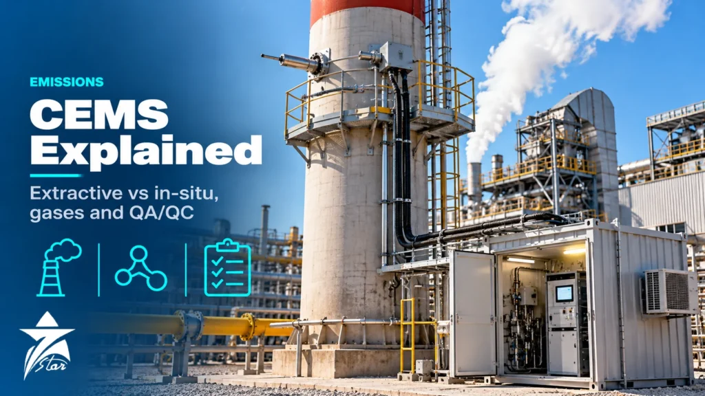
Every fired heater, gas turbine, boiler and sulphur recovery unit with an environmental permit eventually needs continuous emission monitoring, and the system chosen at the design stage decides how much maintenance effort, data loss and audit pain the plant carries for the next fifteen years. A CEMS that looks cheap on the bid sheet can lose its data availability to blocked probe filters, condensate in the sample line or an analyzer that drifts every week in a hot shelter. This guide explains how extractive and in-situ systems differ, which gases and parameters are typically measured, which analyzer principles fit each component, and how the QA/QC regimes of EN 14181 and US EPA 40 CFR Part 60 keep the data defensible.
What a CEMS Actually Consists Of
A CEMS is not one analyzer. It is a chain: a sampling point chosen for a representative gas profile, a probe or optical path, sample transport and conditioning (for extractive systems), one or more analyzers, a flow and moisture measurement when mass emissions are reported, calibration gas handling, and a data acquisition and handling system (DAHS) that converts raw readings into reference-condition averages and reports exceedances. Each link adds its own uncertainty, and regulators judge the whole chain, not the analyzer datasheet.
Results are normally reported as mg/Nm³ or ppm corrected to a reference oxygen level (for example 3 %, 6 % or 15 % O2 depending on the source type) and on a dry basis. That is why almost every CEMS includes an oxygen measurement and, if the analyzers see wet gas, a moisture measurement as well.
Gases and Parameters Typically Measured
The permit defines the list, but the following parameters cover most refinery, power and petrochemical stacks in the GCC:
- SO2 – sulphur recovery units, fuel-oil and sour fuel-gas firing; measured by NDIR, NDUV or UV fluorescence (the latter mostly in dilution systems).
- NOx (NO + NO2) – gas turbines, heaters and boilers; chemiluminescence after an NO2-to-NO converter, NDUV, or NDIR for NO only.
- CO – combustion quality indicator and a permit limit on many turbines; NDIR or gas-filter correlation.
- O2 – reference correction; paramagnetic in extractive systems, zirconia in in-situ probes.
- CO2 – diluent and, increasingly, for greenhouse-gas reporting; NDIR.
- HCl, HF and NH3 – incinerators and SCR ammonia slip; need hot-wet extractive FTIR or in-situ tunable diode laser (TDL) because they dissolve in condensate.
- Total organic carbon (TOC/VOC) – heated flame ionisation detector (FID).
- Dust/particulate – opacity, light scattering or probe electrodynamic monitors, calibrated against isokinetic sampling.
- Volumetric flow, temperature, pressure and moisture – needed to convert concentration into kg/h or tonnes per year.
System Architectures: Extractive and In-Situ
Extractive systems: cold-dry, hot-wet and dilution
Extractive systems pull a continuous sample out of the stack and analyse it in a shelter or cabinet. Three architectures dominate, and the choice depends mainly on the components and on how soluble they are in water.
Cold-dry extractive
A heated probe with a ceramic or sintered filter feeds a heated sample line held above the acid dew point, commonly around 180 °C. In the shelter a sample cooler drops the gas to a stable dew point of a few °C so the analyzers see dry gas. It is the most common design for SO2, NOx, CO, CO2 and O2 and works with robust, well-understood analyzers. Its weakness is the condensate: soluble gases such as SO2 and NO2 can be partly lost if the cooler design is poor, and HCl or NH3 are effectively stripped out.
Hot-wet extractive
Everything from the probe to the analyzer cell stays hot, typically with a heated FTIR or a heated FID. Nothing condenses, so water-soluble and reactive species survive, and moisture can be measured in the same instrument. The price is a heated cell, heated pumps and more complex maintenance.
Dilution extractive
A critical orifice and an eductor at the probe dilute the sample with clean, dry air at a fixed ratio, often somewhere between 50:1 and 250:1, so the diluted gas sits below its dew point and can travel in unheated tubing. Ambient-air-type analyzers then measure the low concentrations. Dilution systems are widespread on large US power plants but need very clean dilution air and careful compensation for the temperature and pressure sensitivity of the orifice.
In-situ systems: probe and cross-stack
In-situ analyzers measure inside the duct without removing a sample. A point or probe in-situ system places the measuring cell at the end of a probe (the zirconia O2 probe is the classic example). A cross-stack or path system shines a beam across the full duct diameter; DOAS for SO2/NOx and TDL analyzers for O2, NH3, HCl and H2O are the usual technologies. US EPA performance specifications distinguish point CEMS from path CEMS by whether the measured path is shorter or longer than 10 % of the equivalent stack diameter.
In-situ systems avoid sample lines and coolers, respond in seconds and measure on a wet basis. In exchange, the analyzer sits on the stack platform exposed to heat, vibration and stack dust, alignment must be maintained, and introducing calibration gas to a cross-duct path is harder than flooding an extractive probe.
Extractive vs In-Situ Compared
| Factor | Cold-dry extractive | Hot-wet extractive | Dilution extractive | In-situ (probe or cross-stack) |
|---|---|---|---|---|
| Measurement basis | Dry | Wet | Wet (diluted) | Wet |
| Soluble gases (HCl, NH3, HF) | Poor – lost to condensate | Good | Fair to good | Good with TDL |
| Analyzer location | Shelter, controlled climate | Shelter, heated cell | Shelter, ambient-level analyzers | Stack platform |
| Main maintenance points | Probe filter, heated line, cooler, pump | Heated components, FTIR optics | Dilution air quality, orifice, eductor | Optics purge, alignment, window cleaning |
| Full-system calibration | Easy – gas at probe | Easy – gas at probe | Easy – gas at probe | Harder – flow-through cells or gas cells |
| Response time | Tens of seconds to minutes | Tens of seconds | Tens of seconds | Seconds |
| Typical fit | Turbines, boilers, heaters | Incinerators, SCR slip, multi-component | Large utility stacks | Large ducts, fast control, NH3 slip |
Choosing an Analyzer Principle for Each Component
Match the principle to the gas, the range and the interference matrix rather than to a brand. A turbine burning sweet gas with NOx limits in the low tens of mg/Nm³ needs a low-range NOx channel with good resolution near zero, while a sulphur recovery tail-gas incinerator needs a wide SO2 range and corrosion-resistant wetted parts. Manufacturers such as Siemens, ABB, SICK, Emerson and Horiba publish suitability-tested ranges; check that the certified range covers about 1.5 to 2.5 times the daily emission limit, the usual target under EN 14181 practice. For a broader look at oxygen, moisture and combustion analyzers on process duty, see our guide to process gas analyzers for refineries and gas plants.
Sampling Location and System Design
- Choose a straight section with a homogeneous profile; EN 15259 and US EPA Method 1 both give guidance on distances from bends, dampers and fans, with eight diameters downstream and two upstream as the classic preferred case.
- Provide a platform, power, instrument air and a dedicated test port next to the CEMS probe so the reference-method team can sample in parallel.
- Keep heated lines continuously heated, sloped and supported; a single cold spot causes condensation and acid corrosion.
- Specify a probe blow-back for dusty stacks and size the probe filter for the particulate load.
- Route calibration gas to the probe, not only to the analyzer inlet, so the whole sample path is tested.
- Use a temperature-controlled, dust-sealed shelter; analyzer drift in a 50 °C enclosure with failing air conditioning is one of the commonest causes of lost data in the region.
QA/QC Under EN 14181 and US EPA Part 60
Two regulatory families shape most specifications seen in Oman and the wider GCC, and many permits reference one or the other.
EN 14181 (European approach)
- QAL1 – the analyzer is suitability-tested and certified, normally under EN 15267, and its total uncertainty is shown to be well inside the permitted uncertainty.
- QAL2 – after installation the CEMS is calibrated against a standard reference method (for example EN 14792 for NOx or EN 14791 for SO2) using a series of parallel measurements, producing a calibration function and a valid calibration range.
- QAL3 – ongoing zero and span checks plotted on control charts by the operator to detect drift and loss of precision.
- AST – the annual surveillance test that confirms the QAL2 calibration function is still valid.
US EPA 40 CFR Part 60
Appendix B performance specifications govern initial certification. Under Performance Specification 2 for SO2 and NOx, calibration drift is checked once a day for seven consecutive days and must stay within 2.5 % of span, and a relative accuracy test audit (RATA) against reference methods such as EPA Method 6C and 7E must generally meet a relative accuracy of 20 % of the reference-method mean, or 10 % of the emission standard when emissions are low. Appendix F, Procedure 1, then sets ongoing QA: daily calibration drift checks, quarterly cylinder gas audits or relative accuracy audits, and an annual RATA.
Whichever regime applies, the data system must flag out-of-control periods, invalid data and maintenance time, because data availability is itself usually a permit condition.
Continuous Emission Monitoring Mistakes That Cost Data Availability
- Specifying a cold-dry system and then adding HCl or NH3 to the permit list later.
- Calibrating only at the analyzer inlet, so leaks and absorption in the sample line go unnoticed.
- Selecting an analyzer range far above the emission limit, which inflates uncertainty at the levels that matter.
- Ignoring calibration gas logistics: certified cylinders with traceable uncertainty, regulators and expiry dates must be planned, not bought in a hurry before an audit.
- Undersizing shelter cooling and dust filtration for summer conditions.
- Treating the DAHS as an afterthought; averaging, O2 correction and substitution rules must match the permit wording exactly.
Maintenance and Troubleshooting
Most CEMS faults trace back to the sample path. A slow response after a span check usually points to a partly blocked filter or a leak; readings that sag in summer afternoons suggest shelter temperature problems; SO2 that reads low against the reference method in a cold-dry system often means absorption in the cooler condensate. Keep a spares list covering probe filters, pump diaphragms, heated-line controllers, cooler peristaltic pump tubes, O2 cells and FTIR or NDIR source lamps. Our instrument calibration program guide explains how to set intervals and keep traceability records that auditors accept.
GCC Conditions for Continuous Emission Monitoring
- Ambient temperatures around 50 °C on stack platforms: confirm the operating limits of in-situ heads and use sunshades or cooled housings.
- Fine dust and sandstorms: positive-pressure purge on optics and good shelter filtration.
- Coastal humidity and salt: stainless or coated enclosures and attention to cable gland sealing.
- Sour service: H2S and SO2 in sulphur plants attack non-resistant wetted materials; check probe and line materials.
- Hazardous areas: if the shelter or probe sits in a classified zone, analyzers and heaters need suitable Ex protection and purge systems.
CEMS Specification Checklist
- Permit parameters, emission limits, reference O2 and dry/wet basis
- Applicable QA standard (EN 14181/EN 15267 or EPA Part 60/75) and certified ranges
- Flue gas composition, temperature, pressure, moisture and dust load
- Stack diameter, sampling location and port availability
- Extractive or in-situ architecture and analyzer principle per component
- Calibration gases, concentrations and delivery point
- Shelter cooling, power, instrument air and hazardous-area classification
- DAHS reporting rules, averaging periods and interface to the plant DCS
- Spare parts and consumables list for at least two years of operation
Stack Measurement Products We Supply
These examples cover part of a CEMS measurement chain, from the analyser to the stack flow measurement.
| Product | Type | Where it fits |
|---|---|---|
| ABB Endura AZ40 Oxygen and Carbon Monoxide Analyzer | O2 and CO analyser | Combustion control and emission monitoring. |
| ABB Endura AZ25 Combustion Gas Oxygen Analyzer | Combustion O2 analyser | Boiler and furnace combustion control. |
| ABB Stack gas flow metering system StackFlowMaster FPD580 | Stack gas flow metering system | Stack flow for mass emission calculation. |
Send the components to measure, the stack conditions and the regulatory requirements through our quote request form.
Sourcing CEMS Analyzers and Spares Through Seven Star LLC
Seven Star LLC supplies stack gas analyzers, sample conditioning parts and accessories on request for plants in Oman and the GCC. Browse our gas analyzer systems and gas analyzer accessories, or the wider analyzer systems range. We help with selection and cross-checking part numbers against your existing system, and availability and lead time are confirmed at quotation.
Upgrading a CEMS or hunting for a probe filter, cooler or O2 cell? Send us the analyzer nameplate, the system tag list or your RFQ and we will come back with matched options and a clear quotation.
Frequently asked questions
What is the difference between extractive and in-situ CEMS?
An extractive CEMS draws a sample out of the stack, conditions it and analyses it in a shelter, which makes full-system calibration easy. An in-situ CEMS measures inside the duct with a probe or a beam across the stack, so there are no sample lines, but the analyzer sits on the platform and is harder to calibrate with gas.
Why do incinerators often need hot-wet CEMS?
HCl, HF and NH3 dissolve in water, so a cold-dry system loses them in the cooler condensate. A hot-wet system keeps the whole sample path above the dew point, typically with a heated FTIR, so these gases reach the analyzer intact and moisture can be measured at the same time.
What are QAL1, QAL2 and QAL3 in EN 14181?
QAL1 is the suitability certification of the analyzer, usually under EN 15267. QAL2 is the on-site calibration against a standard reference method after installation, and QAL3 is the operator's ongoing zero and span drift control using control charts. An annual surveillance test (AST) confirms the QAL2 calibration remains valid.
What does a RATA test check?
A relative accuracy test audit compares CEMS readings with simultaneous reference-method measurements over a series of test runs. Under US EPA Performance Specification 2 the relative accuracy for SO2 and NOx generally has to be within 20 % of the reference-method mean, or within 10 % of the emission standard when emissions are low.
Why is oxygen measured in almost every CEMS?
Emission limits are usually expressed at a reference oxygen level, such as 3 %, 6 % or 15 % O2 depending on the source. The measured oxygen is used to correct the pollutant concentration so that dilution with excess air cannot make emissions look lower than they are.
What information is needed to quote a CEMS analyzer or spare part?
For spares, the analyzer nameplate with model and serial number and the part number from the manual are the most useful. For a new system, provide the permit parameters, emission limits, flue gas composition, temperature, moisture, stack size and the QA standard that applies.
Was this guide helpful?One click helps us write better guides for engineers.
Thank you! Glad it helped. Need this equipment for your project? Request a quotation
Thank you. We will use this to improve the guide.