RT 101 thermostat: 25 to 90 C control with a sensor that survives 300 C
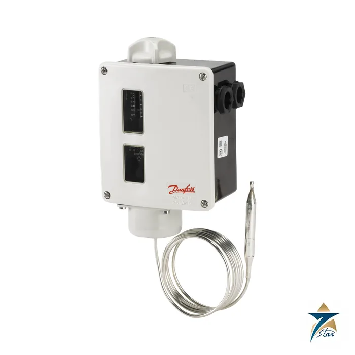
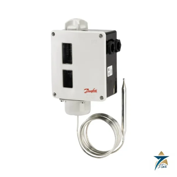
Danfoss 017-150066 is an RT 101 thermostat for heating circuits and warm process temperatures. A 9.5 x 80 mm remote bulb on a 2 m capillary reports to an SPDT snap contact in an IP66 housing. The scale runs 25 to 90 C, which is the typical band for hot-water circuits, heat-exchanger secondary loops, oil preheaters and machinery cooling water, and the bulb can be exposed to 300 C without permanent change. That large safety margin is the distinguishing feature of the RT 101 compared with lower-range types.
The approvals printed for this code include BV, DNV, GL and NKK alongside CE, EAC and UA, reflecting the RT series claim of availability with all major marine approvals.
Technical specifications
| Parameter |
Specification |
| Danfoss code number |
017-150066 |
| Type |
RT101 |
| Function |
Thermostat with remote bulb, automatic reset |
| Temperature range |
25 to 90 C |
| Differential (adjustable) |
2.4-10 C at minimum setting; 3.5-20 C at maximum setting |
| Contact system |
SPDT |
| Contact rating |
AC15=3 A, 400 V; AC1=10 A, 400 V; AC3=4 A, 400 V; DC13=12 W, 220 V; LR=28 A, 400 V |
| Enclosure |
IP66 |
| Sensor |
Remote bulb 9.5 x 80 mm, adsorption charge |
| Capillary tube length |
2000 mm |
| Min. sensor pocket length |
112 mm |
| Max. sensor temperature |
300 C |
| Ambient temperature |
-50 to 70 C |
| Cable entry |
2 x Pg 13.5, screwed |
| Approvals as listed |
BV; CCC; CE; CMIM; DNV; EAC; GL; LVD; NKK; RoHS; RoHS China; TYSK; UA |
| Net weight |
0.847 kg |
| EAN |
5702423119127 |
Differential and sensing behaviour
The differential is adjustable and widens as the scale pointer moves up: 2.4 to 10 C at the bottom of the scale, 3.5 to 20 C at the top. For a closely held heating loop set the pointer in the lower half and the differential spindle to its minimum; for a tank heater, accept a wider differential to protect contactors from too many cycles.
Insert the bulb in a pocket at least 112 mm long, or clamp it into the flow, and make sure the capillary is routed away from hot pipework. Because the charge is adsorption-type, the bulb can be mounted above or below the control head without affecting the reading.
Wiring, limits and ordering notes
The ambient range of -50 to 70 C allows installation on outdoor skids; cable entry is via two Pg 13.5 glands. Contact data in the table are for the AC15 and AC1 duties, so use a relay or contactor for pumps and heaters. The installation guide for the RT 101 and RT 102 thermostats shows the terminals and the mounting dimensions.
Variants with 3, 5, 8 and 10 m capillaries, with different contact functions and with a 1.0 bar test valve exist, each under its own code number; this page covers 017-150066 only. Seven Star LLC is an independent supplier in Muscat; request availability with the code and quantity.
We prefer to confirm the application before quoting 017-150066: the medium or load, the supply or pressure, the ambient temperature and the standards that apply. A short message with these points avoids the wrong variant being ordered and keeps the project schedule safe.
If 017-150066 is needed for an urgent repair, say so in your first message and name the machine that is stopped. We will check what can be confirmed quickly, although delivery times are never promised until the supplier has answered the enquiry in writing.
Selection checks for the RT 101 (017-150066)
Begin with the temperature the thermostat must switch at and make sure it sits comfortably inside the 25 to 90 C scale rather than at either end, where setting and reading the pointer is less convenient. Decide whether the contact should open or close on rising temperature, since the SPDT contact allows either arrangement through the choice of terminals. Check the electrical load against the contact ratings in the table; where the circuit switches a motor, heater bank or other heavy load, plan a contactor or interposing relay. Confirm that the 2 m capillary is long enough to reach from the sensing point to a sensible mounting position for the control head without sharp bends or strain, and that a suitable sensor pocket is available or can be fitted.
Installation and commissioning
Mount the control head on a firm, vibration-free surface where the scale can be read and adjusted, and fit the cable through the screwed entries so that the IP66 protection is maintained. Coil any surplus capillary neatly and fix it so it cannot rub or be crushed; a damaged capillary means the thermostat no longer senses correctly. Place the bulb where it sees a representative temperature, for example in the flow rather than in a dead leg of the pipe, and make sure it is fully inserted in the pocket.
During commissioning, set the range and differential, then bring the process up to temperature and note the actual switching points with a calibrated reference thermometer near the bulb. Adjust if needed and record the final settings for the maintenance file. Where the thermostat acts as a limit rather than a controller, test the trip by raising the temperature in a controlled way and confirm that the connected equipment responds as intended.
Using the thermostat in Oman and the GCC
Hot-water systems, oil preheaters and machinery cooling circuits in the region often sit in plant rooms or on outdoor skids with high summer temperatures. The wide ambient range listed above helps, but avoid placing the control head in direct sun or next to hot surfaces, and route the capillary away from heat sources so that it does not influence the reading. In dusty locations keep the cover and cable glands properly closed; on coastal and marine installations, where humid salt air is common, check the housing and glands periodically for corrosion and moisture. A yearly check of the switching point against a reference thermometer is a sensible part of routine maintenance.
Documents and quotation
The Danfoss RT thermostat data sheet AI555726775232 is attached in its original form. See temperature instrumentation for other thermostats and sensors.










Reviews
There are no reviews yet.