- Automation & ControlView all 1,840 products
- AC Drives
- PLC & I/O Cards
- Industrial Communications
- Vibration Monitoring
- Automation Accessories
- Controllers & Data Acquisition
- Isolator & Barrier
- CCTV & Security
- Safety Switches & Guard Locking
- Encoders
- HMI Displays
- Industrial Computers
- Servo Drives
- Motor Soft Starters
- Pneumatic Cylinders
- Machine Vision
- Automation Software
- Robotics
















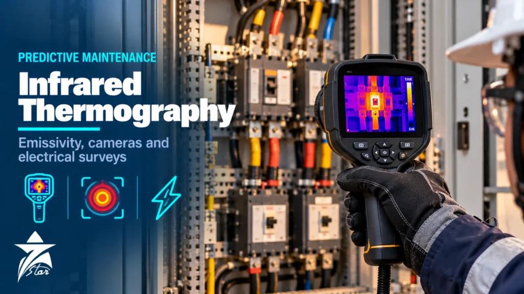
An infrared thermography inspection finds loose connections, overloaded circuits, failing bearings, misaligned couplings, blocked cooler tubes and failed steam traps before they cause a trip, a fire or a forced outage. It is non-contact, done with equipment running, and quick enough to cover a whole substation or pump house in a shift. It is also easy to do badly: a shiny busbar reads cold when it is hot, sunlight on a cable tray looks like a fault, and a lightly loaded breaker hides a bad connection. This guide explains the physics that matters in practice, when an infrared thermometer is enough and when you need a thermal camera, how to deal with emissivity and reflections, how to run electrical and mechanical surveys, how to rate severity, and what to watch for in hot, sunny GCC plants.
How Infrared Temperature Measurement Works
Every object above absolute zero emits infrared radiation, and the amount rises steeply with temperature. An infrared instrument collects this radiation through optics, focuses it on a detector and converts it into a temperature using a calibration curve. Most maintenance cameras and many spot thermometers work in the long-wave band of roughly 8–14 µm, where atmospheric absorption is low at normal working distances.
The instrument does not measure temperature directly. It measures the radiation arriving from the target direction, which is a mix of:
- Radiation emitted by the target, which depends on its temperature and emissivity.
- Radiation reflected by the target from its surroundings (lights, the sun, hot pipes, your own body).
- Radiation transmitted through the target, which is negligible for metals and most solids at these wavelengths.
To get a correct temperature, you must tell the instrument the target emissivity and the reflected apparent temperature. If the emissivity is low, the reflected part dominates and the reading becomes unreliable regardless of the camera’s quality.
Infrared Thermometers vs Thermal Cameras
| Feature | Infrared spot thermometer | Thermal imaging camera |
|---|---|---|
| Output | One averaged reading per spot | Full image with thousands of measured points |
| Finding unknown hot spots | Slow, easy to miss small defects | Fast, shows patterns and comparisons |
| Spatial resolution | Defined by distance-to-spot ratio (D:S) | Defined by detector resolution and lens field of view |
| Documentation | Manual recording | Radiometric images stored for reports and trending |
| Typical use | Quick checks of known points, bearing housings, motor frames, pipe surfaces | Electrical surveys, mechanical routes, refractory, insulation, steam systems |
| Skill needed | Low for basic use | Higher, interpretation requires training |
The distance-to-spot ratio is the most misunderstood specification on spot thermometers. A 12:1 instrument measures a spot about 1 unit wide at 12 units distance. If the spot is larger than the target, for example a small cable lug seen from across a room, the reading averages the lug with the cooler background and understates the temperature. The laser pointer only shows the centre of the spot, not its size.
For cameras, look at detector resolution, the field of view of the lens, thermal sensitivity (NETD) and the measurement range. Higher resolution lets you measure smaller targets from a safe distance, which matters for overhead lines, high-voltage switchyards and anything behind barriers. The portable test and measurement category covers both instrument types.
Emissivity and Reflections in Practice
Emissivity values range from near 0 to near 1. Typical behaviour:
- High emissivity (around 0.9 and above): painted surfaces, most plastics and rubber, electrical insulating tape, heavily oxidised steel, concrete, skin. Readings are reliable.
- Medium emissivity: lightly oxidised metals, some cast iron surfaces. Readings depend on the surface condition.
- Low emissivity (often 0.1 and below): polished or bright aluminium, copper, stainless steel, tin-plated busbars, galvanised surfaces in good condition. Readings are unreliable and dominated by reflections.
Practical techniques:
- Measure on a high-emissivity part next to the bare metal: the insulation, a painted lug, a dirty or oxidised area, or a piece of electrical tape applied during a planned outage.
- Set the reflected apparent temperature by measuring a crumpled aluminium foil reflector at the target position with emissivity set to 1.0.
- Change your viewing angle. A reflection moves when you move; a real hot spot does not.
- Keep the viewing angle within about 30–45° of perpendicular where possible, because emissivity of many surfaces drops at grazing angles.
- Treat qualitative findings (this phase is hotter than the other two) as more reliable than absolute temperatures on low-emissivity surfaces.
Electrical Inspections
Electrical connections fail by increasing resistance: loose bolts, corrosion, undersized lugs, damaged contacts. Heat generated is proportional to the square of current times resistance, so a defect becomes visible only when current flows. Key rules:
- Load: inspect at normal operating load. NFPA 70B (2023 edition), which now requires annual infrared inspection of electrical equipment, permits inspection at not less than 40% of nominal circuit loading where normal load is not feasible, and requires the load to be recorded.
- Line of sight: cameras do not see through panel covers or ordinary glass. Panels must be opened under a safe work procedure with appropriate arc flash precautions (for example, following NFPA 70E or local equivalent), or fitted with infrared windows suited to the camera.
- Compare like with like: compare the three phases of the same circuit, or identical breakers under similar loads. This avoids the uncertainty of ambient and emissivity.
- Look for patterns: a hot spot at a connection with heat conducting away along the cable suggests a high-resistance joint; a whole phase evenly warm suggests overload or imbalance; a warm neutral suggests harmonics.
Typical targets: incoming terminations, breaker line and load connections, busbar joints, fuse clips, contactor and overload relay terminals, cable lugs, transformer bushings and cooling, capacitor banks, VFD input terminals and UPS battery connections. The circuit breakers and contactors and overload relays categories cover the components most often replaced after a survey.
Severity Criteria
Severity ranking turns images into maintenance priorities. The NETA Maintenance Testing Specifications are widely used. For comparisons between similar components under similar load, the commonly applied tiers are a difference of 1–3 °C as a possible deficiency warranting investigation, 4–15 °C as a probable deficiency to repair when possible, and more than 15 °C as a major discrepancy requiring immediate repair. NETA also gives criteria for rises over ambient air temperature, but component-to-component comparison is usually more reliable because ambient inside an opened panel is hard to define.
Severity criteria are a starting point, not the whole decision. Consider:
- Load at the time of inspection: a 10 °C rise at 40% load will be much higher at full load.
- Criticality of the equipment and consequences of failure.
- Absolute temperature against the component’s insulation class and rating.
- Trend from previous surveys: a rising difference is more urgent than a stable one.
Mechanical and Process Applications
Thermography complements vibration and oil analysis in mechanical condition monitoring:
- Motors: hot frames from blocked cooling fins, overload, voltage imbalance; hot bearing housings.
- Bearings: a bearing housing warmer than its partner points to lubrication problems, over-greasing or misalignment.
- Couplings and belts: misaligned couplings heat up; slipping belts and pulleys show friction heat.
- Steam traps and lines: a failed-open trap shows steam temperature downstream; a failed-closed trap shows a cold line.
- Heat exchangers and coolers: blocked tubes and fouled fins show as cold sections.
- Refractory and insulation: hot spots on furnace shells, ducting and insulated piping show damaged lining or wet insulation.
- Tanks: liquid and sludge levels often show as temperature boundaries on the tank wall.
For rotating equipment, combine thermal data with vibration data; our guide to vibration monitoring systems explains the online and portable options.
GCC Conditions: Sun, Heat and Dust
Outdoor surveys in the Gulf face strong solar loading. Equipment facing the sun can be tens of degrees warmer than shaded equipment, and dark surfaces heat more than light ones. This can create false hot spots and hide real ones.
- Schedule outdoor electrical surveys before sunrise, after sunset or on the shaded side, while load is still representative.
- Compare components with the same sun exposure and colour.
- Note wind speed: wind cools surfaces and reduces visible temperature differences.
- Check the camera’s operating temperature range; leaving it in a parked vehicle can exceed the limit.
- Keep lenses clean; dust films reduce the signal and blur fine details.
Common Infrared Thermography Inspection Mistakes
- Using a spot thermometer from too far away, so the spot is larger than the target.
- Measuring bare busbars or stainless steel at the default emissivity of 0.95.
- Mistaking a reflection of a light fitting or the sun for a hot spot.
- Surveying at night shift with plant lightly loaded and reporting “no defects”.
- Reporting absolute temperatures without load, emissivity and ambient conditions.
- Leaving findings in a report without a work order and a repeat scan after repair.
Building an Infrared Thermography Inspection Programme
A thermography programme works best when it is part of the maintenance system, not a once-a-year event:
- Build an equipment list with criticality, location and access requirements.
- Define routes and intervals (annual minimum for electrical equipment, more often for critical assets).
- Use a standard report format recording load, emissivity, reflected temperature, ambient, wind and severity.
- Raise work orders for each finding and re-scan after repair to confirm the fix.
- Train and qualify personnel; ISO 18436-7 defines thermographer qualification levels, and ISO 18434-1 gives general procedures for thermography in condition monitoring.
- Verify instrument accuracy periodically against a blackbody reference as part of your instrument calibration programme.
Instrument Selection Checklist
- Main use: electrical surveys, mechanical routes, process or building inspection
- Spot thermometer D:S ratio or camera detector resolution and lens options
- Thermal sensitivity (NETD) and temperature range including high-temperature range if needed
- Adjustable emissivity and reflected temperature compensation
- Radiometric image storage, reporting software and data export
- Focus type (manual focus gives sharper measurements than fixed focus)
- Operating temperature range and housing rating for hot, dusty sites
- Battery life and spare batteries for full survey days
- Accessories: telephoto lens, IR windows for switchgear, calibration certificate
Thermal Cameras We Supply
These examples cover handheld inspection cameras and fixed monitoring cameras.
| Product | Type | Where it fits |
|---|---|---|
| FLIR E54 Advanced Thermal Imaging Camera | Thermal imaging camera | Routine electrical and mechanical inspection. |
| FLIR E96 Advanced Thermal Imaging Camera | Advanced thermal imaging camera | Detailed inspection. |
| FLIR T540 Professional Thermal Imaging Camera | Professional thermal imaging camera | Detailed inspection and reporting. |
| testo 868 Thermal Imager with SuperResolution | Thermal imager | Building and maintenance checks. |
| Axis Q2101-TE Thermometric Thermal Camera for Temperature Monitoring | Thermometric thermal camera | Continuous monitoring of fixed equipment. |
| Axis Q1961-XTE Explosion-Protected Thermal Camera for Zone 2 and Division 2 | Explosion-protected thermal camera | Continuous monitoring in hazardous areas. |
Send the targets, distance and temperature range through our quote request form.
Sourcing Infrared Thermometers and Thermal Cameras Through Seven Star LLC
Seven Star LLC supplies infrared thermometers, thermal imaging cameras, infrared inspection windows and related accessories on request from manufacturers such as Fluke, FLIR (Teledyne FLIR), Testo and Optris. We help with selection, comparing specifications for your application and cross-checking part numbers for lenses, batteries and accessories; availability and lead time are confirmed at quotation.
Send us your application, the equipment you need to inspect and any current instrument model or datasheet, and we will prepare a quotation for a suitable infrared thermometer or thermal camera.
Frequently asked questions
What is the difference between an infrared thermometer and a thermal camera?
An infrared thermometer measures the average temperature of one spot, whose size depends on the distance-to-spot ratio. A thermal camera measures thousands of points at once and shows them as an image, so hot spots, patterns and comparisons between phases are visible immediately. Spot thermometers are useful for quick checks of known points; cameras are needed for surveys where you do not know in advance where the problem is.
Why does emissivity matter in infrared measurement?
Emissivity is the fraction of radiation a surface emits compared with a perfect emitter at the same temperature. Shiny metals such as polished aluminium or copper emit very little and reflect their surroundings, so the instrument reads them far too low or picks up reflections. Painted, oxidised or taped surfaces have high emissivity and give reliable readings.
How much load is needed for an electrical thermography survey?
Heat from a poor connection rises with current, so surveys should be done at normal operating load. NFPA 70B (2023 edition) permits inspection at not less than 40% of nominal circuit loading where normal loading is not feasible, with the loading documented. Results at low load understate the severity of a defect.
Can thermal cameras see through glass or panel covers?
No. Ordinary glass and most plastics are opaque in the long-wave infrared band used by most maintenance cameras, so the camera sees the cover surface, not the components behind it. Panels must be opened under a safe work procedure, or fitted with infrared inspection windows designed for the camera's waveband.
How often should infrared inspections be carried out?
NFPA 70B (2023) requires infrared inspection of electrical equipment at least annually, with more frequent inspection for critical or heavily loaded equipment. Mechanical surveys of motors, bearings and couplings are often added to route-based condition monitoring at monthly or quarterly intervals. The interval should reflect the criticality of the asset and its failure history.
What qualifications should a thermographer have?
ISO 18436-7 defines qualification and assessment requirements for personnel performing thermography for condition monitoring, at increasing category levels. Training covers heat transfer, emissivity, reflections and interpretation as well as camera use. Many asset owners require a certified thermographer for electrical surveys used in insurance or compliance records.
Was this guide helpful?One click helps us write better guides for engineers.
Thank you! Glad it helped. Need this equipment for your project? Request a quotation
Thank you. We will use this to improve the guide.