- Automation & ControlView all 1,840 products
- AC Drives
- PLC & I/O Cards
- Industrial Communications
- Vibration Monitoring
- Automation Accessories
- Controllers & Data Acquisition
- Isolator & Barrier
- CCTV & Security
- Safety Switches & Guard Locking
- Encoders
- HMI Displays
- Industrial Computers
- Servo Drives
- Motor Soft Starters
- Pneumatic Cylinders
- Machine Vision
- Automation Software
- Robotics
















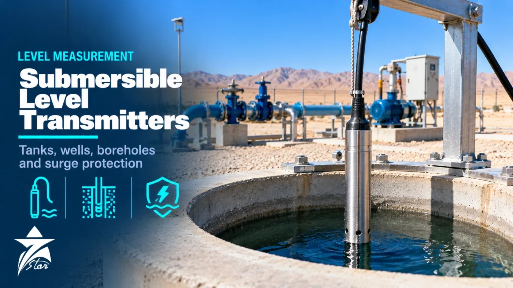
A submersible level transmitter is the simplest way to measure level in places where a top-mounted sensor struggles: deep boreholes, narrow wells, underground reservoirs, irrigation ponds and water tanks with foam or condensation in the headspace. You lower a sealed pressure sensor on its cable, the water column pushes on the diaphragm, and a 4–20 mA signal comes back up. The idea is easy, but in the field most failures come from the details: a vent tube full of water, a cable chewed by the pump riser, a lightning surge on a 300 m signal run, or a stainless housing pitted by warm brine. This guide covers how hydrostatic sensors work, how to size range and specify cable, materials for seawater and wastewater, installation in tanks and boreholes, surge protection, and what to check when readings drift.
How Hydrostatic Level Measurement Works
The pressure at the bottom of a liquid column equals density × gravitational acceleration × height (p = ρ·g·h). For fresh water at room temperature, 1 bar of pressure corresponds to about 10.2 m of water, so a sensor ranged 0–1 bar covers about 10 m of level and a 0–4 bar sensor covers about 40 m. The transmitter only sees pressure. It reports level correctly only if the density it was scaled with matches the actual liquid.
Density matters more than many people expect. Seawater is roughly 2.5% denser than fresh water, so a probe scaled for fresh water will read seawater level about 2.5% high. Hot water is slightly less dense than cold water, and brine or reject water from a reverse osmosis plant can be noticeably denser again. If the liquid density changes over the day, the level error changes with it.
The sensing element is usually a piezoresistive silicon cell behind a stainless steel or titanium isolating diaphragm, or a dry ceramic capacitive cell. Ceramic cells tolerate abrasion and overload well and are common in wastewater. Piezoresistive cells with oil-filled isolation give small diameters and good accuracy for boreholes.
Gauge Reference and Why the Vent Tube Matters
Almost every submersible level transmitter is a gauge-pressure device. It needs to compare the pressure under water with the atmospheric pressure acting on the liquid surface. The cable therefore carries a small vent tube (capillary) that runs from the back of the sensing diaphragm to the cable end in the junction box. Barometric pressure changes reach both sides of the diaphragm and cancel.
Barometric pressure changes by several millibar with normal weather, and each millibar is about 1 cm of water. In a reservoir where you control pumps on a 10 cm deadband, an unvented or blocked sensor will cycle pumps on the weather rather than on the water.
The vent is also the weak point. Warm, humid air moving in and out of the tube condenses inside it, and once water reaches the diaphragm the sensor drifts or fails. Protection options:
- A breather filter or membrane cap at the cable end, which lets air through but stops liquid water and dust.
- A desiccant cartridge or bellows-type vent element on the junction box, replaced when the indicator colour changes.
- Terminating the cable in a ventilated, shaded enclosure rather than a sealed box that heats up in the sun.
- Never cutting the cable and splicing it in a pit where the vent can flood. If you must extend the cable, use a vented junction box above any possible flood level.
Absolute-pressure submersible loggers with no vent do exist. They need a second barometric sensor at the surface and a calculation to subtract it, which suits data logging in monitoring wells but not real-time pump control.
Types Compared: Which Design Fits Which Job
| Design | Typical use | Strengths | Limitations |
|---|---|---|---|
| Small-diameter stainless probe (around 16–25 mm) | Boreholes, monitoring wells, narrow stilling tubes | Fits small casings, good accuracy, light | Small diaphragm fouls easily in dirty water |
| Ceramic-cell probe with plastic or stainless body | Wastewater, wet wells, sludge, tanks with solids | Robust diaphragm, good overload tolerance | Larger diameter, cell can crack from impact |
| Titanium probe | Seawater intakes, brine, reject water, warm saline groundwater | Strong resistance to chloride pitting | Higher cost, longer lead time |
| Flush large-diaphragm probe | Viscous or fouling liquids, slurries | Less build-up, easy to clean | Bulky, not for narrow casings |
| Probe with integrated temperature sensor | Groundwater studies, hot tanks | Extra measurement on the same cable | More conductors, slightly larger cable |
| Externally mounted hydrostatic transmitter at tank base | Above-ground tanks with a bottom nozzle | No cable in the liquid, easy access | Needs isolation valve and a nozzle below the lowest level |
For pressurised or closed tanks, a submersible gauge probe will not work because the gas above the liquid is not at atmosphere. In that case use a differential pressure arrangement or a radar transmitter instead.
Sizing the Range Correctly
Ranging errors are common. A sensor ranged far above the real water column loses resolution, and one ranged too low saturates or is damaged by surges. Collect these values before selecting:
- Maximum liquid height above the sensor position, including overflow level in tanks and rest water level after recharge in wells.
- Minimum level that must still be read, which sets how low the sensor hangs.
- Liquid density and its range (fresh water, seawater, brine, wastewater).
- Surge or overpressure events: pipe filling, pump start water hammer in a riser, or well development with air lifting.
- Required accuracy in centimetres, not just in percent of span.
Most manufacturers allow the range to be turned down within limits, but accuracy is quoted as a percentage of the sensor’s upper range limit, so a 0–10 bar cell turned down to 0–2 bar will usually perform worse than a native 0–2 bar cell. In boreholes, size the range for the full column from sensor to rest level, and confirm the overpressure rating for the deepest possible installation.
Cable Specification for Long Drops
The cable carries the signal, the vent tube and the weight of the probe. On deep boreholes, the cable choice matters as much as the sensor.
- Sheath material: polyethylene (PE) is cheap and fine for potable water; polyurethane (PUR) has good abrasion resistance; FEP or ETFE fluoropolymer sheaths are used for aggressive chemicals, hydrocarbons and higher temperatures. Check drinking water approvals if the probe sits in potable storage.
- Strain relief: a Kevlar or steel strain member stops the conductors and vent tube from stretching. Hang the probe from a dedicated cable clamp or a suspension wire, never from the cable gland.
- Screen: a braided or foil screen reduces induced noise from pump motor cables that share the same casing.
- Length: order the cable to length with some spare. Splicing a vented cable is possible but each joint is a place for moisture to enter.
- Loop budget: with 4–20 mA, check that the supply voltage minus cable resistance drop and any barrier or surge protector drop still meets the transmitter’s minimum supply at 20 mA.
Materials for Seawater, Brine and Wastewater
In the GCC, many applications are saline: seawater intakes for desalination, brine reject pits, brackish groundwater and cooling water basins. Water temperatures in shallow tanks and intake bays can exceed 35 °C in summer, which speeds up chloride corrosion. 316L stainless steel is a reasonable default for potable and slightly brackish water, but in warm seawater it can pit and suffer crevice corrosion under cable clamps and threads. Titanium bodies and diaphragms are the safer choice for continuous seawater immersion, while ceramic-cell probes with PVDF or similar plastic housings work well in many brines and chemical solutions.
Wastewater adds fats, rags, hydrogen sulphide and biological growth. Hydrogen sulphide attacks copper conductors where the cable enters damp, unventilated junction boxes, so keep terminations in a ventilated enclosure away from the wet-well atmosphere. The liquid analytics category covers the analyzers usually installed alongside level sensors in the same treatment basins.
Installation in Tanks, Wells and Boreholes
Tanks and reservoirs
Hang the probe inside a perforated stilling tube (PVC or HDPE in water service) fixed to the wall. The tube stops the probe swinging in turbulent inflow and keeps it away from mixer and pump suction currents. Leave the probe a short distance above the floor so sediment does not cover it. Avoid installing near the inlet, where incoming flow creates velocity pressure that reads as false level.
Boreholes and wells
Fit the probe into a dedicated access tube (often called a dip tube or sounding tube) strapped to the rising main. This protects the cable from abrasion against the pump riser and allows the probe to be withdrawn without pulling the pump. Set the probe above the pump intake but below the lowest dynamic water level during long pumping, including seasonal decline. Secure the cable at the wellhead with a proper cable hanger and seal the entry so surface water and insects cannot enter the casing.
Open channels and sumps
In sumps and lift stations, a submersible probe often controls duty and standby pumps. Here a redundant float switch for high-high level is good practice, because a fouled or failed probe should not be the only protection against overflow. For level instrumentation in sumps with heavy solids, consider non-contact radar as an alternative; our guide on radar level transmitter selection explains the trade-offs.
Lightning and Surge Protection
Remote wells and reservoirs are often the tallest grounded structures in flat desert terrain, and long signal cables between a borehole and a control panel pick up large induced voltages from nearby strikes. A transmitter submerged in water is effectively earthed at one end, so surge current looks for a path through the electronics.
- Use a transmitter with built-in surge protection where available, and add a separate surge protective device (SPD) for signal lines, selected with reference to IEC 61643-21, at the panel end of the loop.
- On long runs, protect both ends: one SPD near the wellhead and one at the RTU or PLC input.
- Bond the SPD earth, the cable screen and the wellhead casing to a common earthing point with short conductors. A long earth lead makes the SPD useless.
- Follow the site’s lightning protection design to IEC 62305 for the structure itself; the SPD is the last layer, not a substitute.
- Remember that the SPD adds a small voltage drop to the 4–20 mA loop; include it in the loop budget.
Common Mistakes
- Sealing the cable end in an airtight box, which blocks the vent and makes the reading follow barometric pressure.
- Scaling a fresh-water probe and installing it in seawater or brine without correcting density.
- Hanging the probe by its cable from the gland, stretching the conductors and vent tube.
- Dropping the probe into the turbulent zone near an inlet or pump suction.
- Running the signal cable in the same conduit as pump motor cables without a screen.
- Using 316L stainless steel for continuous warm seawater immersion.
Maintenance and Troubleshooting
Plan a routine inspection interval based on how dirty the water is. Clean water reservoirs may need a check once or twice a year; wastewater wet wells may need monthly cleaning. Typical checks:
- Lift the probe and inspect the diaphragm guard for silt, biological growth and scale. Clean with water and a soft brush, never with a hard tool against the diaphragm.
- Inspect the vent filter or desiccant and replace if saturated.
- Compare the transmitter reading with a manual dip tape or a sight point at two different levels. A constant offset suggests zero drift or wrong installation depth; an error that grows with level suggests a span or density issue.
- If the reading follows the weather, suspect a blocked or flooded vent.
- If the output is erratic during pump starts, check screening, earthing and the routing of the signal cable.
- If the output is fixed at a low or high saturation value, check loop voltage, damaged cable and surge damage before replacing the sensor.
The pressure instrumentation category lists the gauge and transmitter types often used as test references when verifying hydrostatic readings.
Specification Checklist
- Application: tank, well, borehole, sump or open channel, and liquid type
- Liquid density and temperature range
- Measuring range in metres of water and required accuracy in centimetres
- Probe diameter limit (casing or dip tube internal diameter)
- Housing and diaphragm material (316L, titanium, ceramic, plastic)
- Cable length, sheath material, strain member and any potable water approval
- Output (4–20 mA, HART, Modbus or SDI-12) and supply voltage
- Vent protection: filter, desiccant or vented junction box
- Surge protection on the transmitter and SPDs at panel and wellhead
- Ingress protection (IP68 at the required depth) and hazardous area certification if needed
- Accessories: cable hanger, stilling tube, junction box, display or controller
Submersible Level Transmitters We Supply
These examples cover hydrostatic probes for tanks, wells and boreholes.
| Product | Type | Where it fits |
|---|---|---|
| Mobrey 9710 Submersible Hydrostatic Level Transmitter 4-20 mA | Submersible hydrostatic level transmitter | Tanks, wells and sumps. |
| Druck PDCR 1800 / PTX 1800 Titanium Submersible Level Pressure Sensor | Titanium submersible level sensor | Corrosive water, seawater and boreholes. |
| JUMO MAERA S25 Hydrostatic Level Probe | Hydrostatic level probe | Water and wastewater level. |
| KELLER Series 26Y Level Probe 4-20 mA 0.1 to 10 bar | Level probe | Groundwater and tank level. |
| Trafag EXNAL 8858 Ex Submersible Pressure Transmitter | Ex submersible pressure transmitter | Hazardous-area tanks and sumps. |
Send the range, cable length, liquid and any hazardous-area requirement through our quote request form.
Sourcing Submersible Level Transmitters Through Seven Star LLC
Seven Star LLC supplies submersible and hydrostatic level transmitters, vented cables, junction boxes and surge protection devices on request from manufacturers such as Endress+Hauser, VEGA, WIKA and KELLER. We help with selection, range and material checks, and cross-checking part numbers against existing installations; availability and lead time are confirmed at quotation.
Send us the existing transmitter nameplate or datasheet, or your well depth, water type and cable length, and we will prepare a quotation for a matching submersible level transmitter.
Frequently asked questions
How does a submersible level transmitter convert pressure to level?
The sensor measures the hydrostatic pressure of the liquid column above its diaphragm, which equals density × gravity × height. For fresh water about 1 bar corresponds to roughly 10.2 m of column, so a 0–1 bar sensor covers about 10 m. The transmitter output is scaled in metres using the liquid density entered at configuration.
Why does a submersible transmitter need a vented cable?
A gauge sensor must compare the water pressure with the atmosphere above the liquid surface. The vent tube inside the cable brings that reference pressure down to the back of the diaphragm, so barometric changes cancel out. Without it, weather-driven pressure swings appear as level changes of several centimetres.
Can I use a submersible level transmitter in seawater or brine?
Yes, but 316L stainless steel housings can suffer pitting and crevice corrosion in warm seawater. Titanium housings and diaphragms, or ceramic sensing elements with a plastic body, are the common choices for seawater intakes, brine pits and reject-water tanks. The cable sheath must also be rated for continuous salt-water immersion.
What causes most submersible level transmitter failures?
The most frequent causes are moisture entering the vent tube, lightning or switching surges on long cable runs, and mechanical damage from pumps or turbulence. Sludge building up on the diaphragm and cable damage at the wellhead entry are also common. Using a vent filter, surge protectors at both ends and a stilling tube removes most of these risks.
How do I size the range of a borehole level sensor?
Start from the deepest expected pumping water level and add a margin for drawdown during long dry periods. The sensor must sit below that level but above the pump intake, and the range must cover the full water column from the sensor up to the highest rest level. Check that the overpressure rating covers surges from well development or pipe filling.
Is a submersible transmitter suitable for wastewater wet wells?
It can work, but grease, rags and solids tend to coat the diaphragm and foul the cable. Many operators prefer a flush or large-diaphragm sensor hung in a perforated stilling tube, or a non-contact ultrasonic or radar sensor above the surface. Where a submersible unit is used, schedule regular lifting and cleaning.
Was this guide helpful?One click helps us write better guides for engineers.
Thank you! Glad it helped. Need this equipment for your project? Request a quotation
Thank you. We will use this to improve the guide.