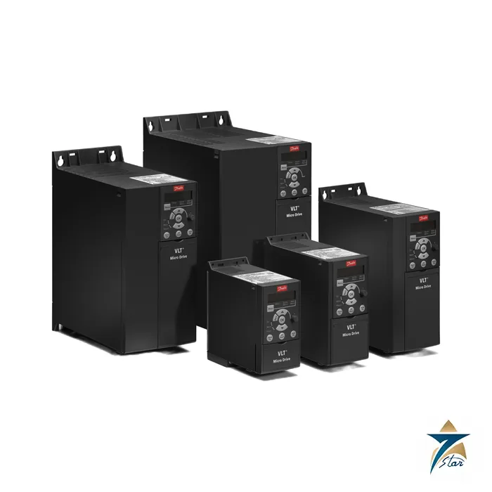
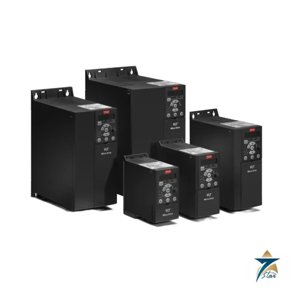
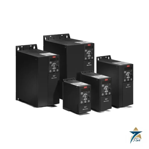
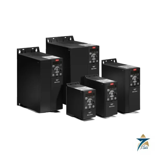
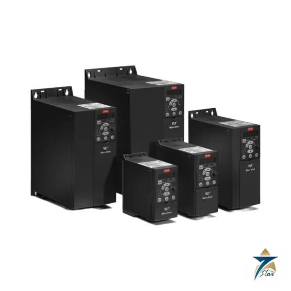
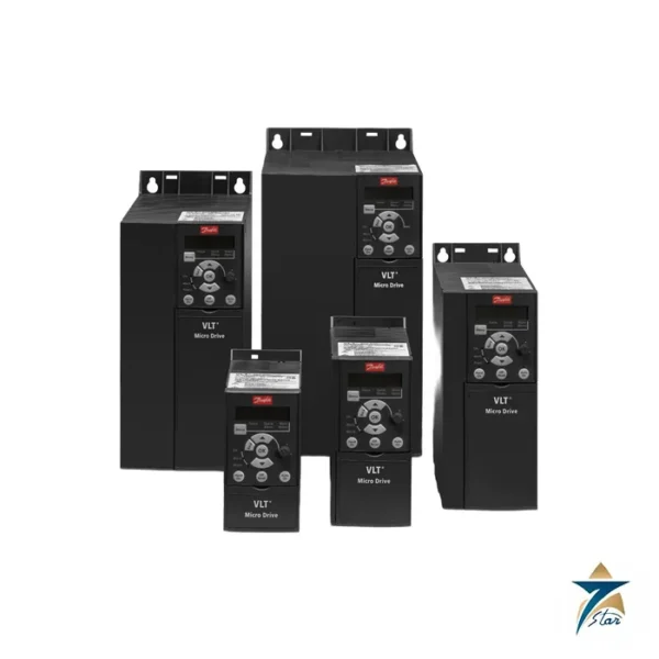
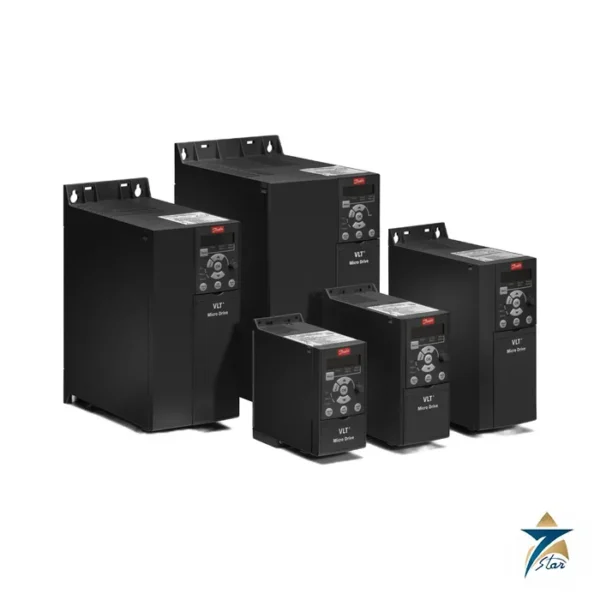
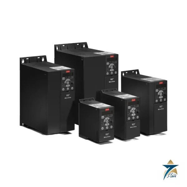
A 3 kW, 400 V VLT Micro Drive in the larger M3 frame with brake chopper
Danfoss order number 132F0024 corresponds to FC-051P3K0T4E20H3BXCXXXSXXX, the 3.0 kW (4 hp) three-phase 380-480 V VLT Micro Drive FC 51 with integrated RFI filter and brake chopper. At 3 kW the FC 51 moves to the M3 frame, 90 mm wide and 239 mm high, which also holds the 4.0 and 5.5 kW ratings in the same enclosure family. A motor of this size is typical for medium circulation pumps, compressors, mixers and machine-tool spindles, and the built-in chopper means a braking resistor can be added without buying a separate brake unit.
This drive is configured with the class A1/B (C1) filter, coated electronics and no local control panel. The M3 frame is also the point at which the 24 V control supply is derated: the design guide gives 100 mA load on terminal 12 for M1 and M2 but 50 mA for M3, which matters when many sensors share the control supply.
Technical specifications
| Parameter |
Specification |
| Order number / type code |
132F0024 / FC-051P3K0T4E20H3BXCXXXSXXX |
| Typical shaft output |
3.0 kW (4 hp) |
| Supply |
3 x 380-480 V AC, +/-10%, 50/60 Hz |
| Motor-side current at 380-440 V |
7.2 A continuous, 10.8 A intermittent |
| Motor-side current at 440-480 V |
6.3 A continuous, 9.5 A intermittent |
| Mains-side current at 380-440 V |
11.5 A continuous, 16.8 A intermittent |
| Mains-side current at 440-480 V |
9.9 A continuous, 14.4 A intermittent |
| Housing |
M3, IP20 chassis |
| Outline H x W x D |
239 x 90 x 194 mm; 294 mm high with decoupling plate |
| Weight |
3.0 kg (design guide) |
| Heat loss, best case / typical |
75.0 W / 101.6 W |
| Efficiency (best / typical) |
98.0% / 97.2% |
| Maximum cable cross-section, mains and motor |
4 mm2 / 10 AWG |
| Danfoss store data |
Net weight 2.915 kg, gross weight 3.215 kg, volume 11.003 l, EAN 5702427357587, ECCN US 3A999.a |
Type code decoded for 132F0024
| Element |
Meaning |
| P3K0 |
3.0 kW / 4 hp |
| T4 |
Three phase 380-480 V |
| E20 |
IP20 chassis |
| H3 |
RFI filter A1/B (C1) |
| B |
Brake chopper included |
| X |
No local control panel |
| C |
Coated PCB |
| X X X |
No mains option, no adaptation A or B |
| SXXX |
Latest standard software |
Choosing and installing the M3 drive
Size the supply from the input current of 11.5 A, and use the maximum cable size of 4 mm2 for mains and motor. The design guide lists accessory codes for this frame: IP21 kit 132B0110, type 1 kit 132B0105, decoupling plate 132B0107 and the MCC 107 line filter 130B2529 listed for 132F0024. The drive trips on motor phase loss, mains phase loss, earth fault and DC-link over or undervoltage, and the thermal motor protection is electronic. Motor cable limits are 15 m screened and 50 m unscreened.
Because 3 kW motors often run on shared pump skids in hot rooms, review the derating curves for 40 °C and above before ordering. Lifecycle: the manufacturer’s store lists this drive with last time buy June 30, 2026 and last time delivery September 30, 2026, together with an upgrade prompt, so ask us to check stock before planning an installation date.
Key features of the VLT Micro Drive FC 51
- Integrated RFI filter – the H3 filter option in this type code limits conducted emissions, which helps when the drive shares a supply with controls and instrumentation.
- Brake chopper on board – an external braking resistor can be connected directly to dissipate regenerative energy from decelerating high-inertia loads.
- Coated circuit boards – the C option adds conformal coating, giving the electronics better resistance to humidity and airborne contaminants.
- Process PI controller – the drive can hold pressure, flow or level from a sensor signal without a separate controller.
- Automatic Energy Optimisation – reduces motor magnetisation at partial load on variable torque applications such as pumps and fans.
- Compact side-by-side mounting – the bookshelf format saves panel width when several drives are installed together.
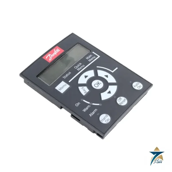
No local control panel: how to programme it
This variant is ordered without the local control panel (LCP). Parameters can be set by fitting an LCP 11 or LCP 12 to the front of the drive when needed, by copying settings from another unit through the panel’s copy function, or through the Danfoss PC software over the RS485 interface. For a plant with several identical drives, configuring one unit and copying the parameter set to the others is the fastest method. One control panel can be kept by the maintenance team and moved between drives, which suits installations where operators should not change settings.
Braking resistor selection
The brake chopper is only useful with a correctly rated resistor. Select the resistor using the Danfoss brake resistor guidance for this power size, taking into account the braking power and duty cycle of the application. Mount the resistor where its heat can escape safely, outside the drive enclosure if possible, and use the resistor protection functions provided in the drive parameters.
Typical applications
- Booster and circulation pumps with pressure or flow control.
- Ventilation fans and small air handling units.
- Conveyors and turntables where controlled stopping is needed.
- Mixers and agitators in process skids.
- Small compressors and machine spindles.
Installation in Oman and GCC conditions
As an IP20 chassis unit, this drive must be installed inside a cabinet. In Oman’s summer conditions, panel temperatures in unconditioned plant rooms can climb quickly, so calculate cabinet cooling from the drive heat loss in the specification table and apply Danfoss derating rules for high ambient temperature and altitude where applicable. The coated PCB is an advantage in coastal and humid locations, but sealed enclosures with filtered ventilation or air conditioning remain the best protection against dust and salt. Check the terminal tightness after the first weeks of operation, since thermal cycling can loosen connections.
Commissioning steps
- Verify supply voltage and earthing before connecting mains.
- Enter motor nameplate data and run the automatic motor adaptation where recommended.
- Set ramp times and speed limits to suit the driven machine.
- Configure the brake resistor parameters if a resistor is fitted.
- Test start, stop and fault reset from the control system before handover.
What to include in your RFQ
Give the order number 132F0024 or the full type code, the quantity, and whether you also need an LCP, the decoupling plate, an IP21 or type 1 kit, a line filter or a braking resistor. For replacements, a photo of the nameplate of the existing drive helps confirm the exact variant.
Documents and quotation
The Danfoss design guide is attached as a download. Also see the Danfoss VLT Micro Drive FC 51 family page and the AC drives category. For a quotation, send the drive label or the motor kW and voltage, and confirm the exact type code with us before ordering.






Reviews
There are no reviews yet.