Air release and vacuum protection in one valve body
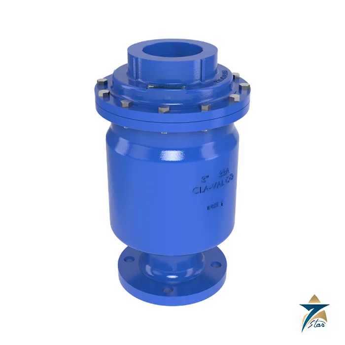
The Cla-Val 33A is a high performance combination air release and vacuum breaker valve designed to protect pipelines and vertical turbine pump applications from air lock and vacuum collapse. It eliminates air and prevents vacuum formation in pipelines. The body is ductile iron with internal and external fusion-bonded epoxy coating, and the datasheet states that it meets AWWA C512 requirements and is tested to seal at 2 psi with Buna-N seals.
The valve is listed for NSF/ANSI 61 and 372 and, as printed on the datasheet, meets the federal mandate limiting lead in drinking water. The entire float poppet system can be replaced without removing the valve body from the pipeline.
Technical specifications
| Parameter |
Specification |
| Model |
Cla-Val 33A combination air release and vacuum breaker valve (33AWS for sea water) |
| Sizes |
1, 2, 3, 4 and 6 in |
| End connections |
Threaded x threaded (1 to 4 in, 300 lb); flanged inlet x threaded outlet (2 to 6 in, 150 / 300 lb); flanged x flanged (6 in, 150 lb) |
| Max. pressure |
300 psi; higher pressures on request for 2, 3 and 4 in |
| Small orifice |
0.076 in standard; 0.125 in optional on 3 and 4 in |
| Body materials |
Epoxy-coated ductile iron ASTM A536 65-45-12; epoxy-coated cast steel ASTM A216-WCB; naval bronze ASTM B61; nickel aluminum bronze ASTM B148; 316, duplex and super duplex stainless steel; bronze (some by request) |
| Internals |
304 stainless steel float (316 or Monel optional); nitrile seals (Viton optional); stainless steel and Delrin parts |
| Temperature |
Water to 180 °F |
| Approvals and compliance as printed |
NSF/ANSI 61 and 372; meets AWWA C512; test to seal at 2 psi (Buna-N) |
| Weight, approx. |
25 lb (1 in threaded), 29 lb (2 in), 38 lb (3 in), 40 lb (4 in), 70 lb (6 in flanged inlet), 75 lb (6 in flanged both) |
| Options |
Hood/screen assembly; throttling device; gooseneck (1 to 4 in); arrestor check (4 and 6 in) |
Operation in air release and vacuum prevent modes
In air release mode the valve is normally open. While the line fills or a pump is started, air is exhausted through the large venting orifice. In normal operation, air accumulates and the float lowers as the water level inside the valve falls, so small amounts of accumulated air are released through the small orifice (0.076 inch standard; 0.125 inch optional on 3 and 4 inch sizes), and the float poppet then closes drip-tight.
In vacuum prevent mode, when line pressure falls below positive pressure and the liquid level drops, the float drops, unseats and admits air into the line so that a vacuum cannot form. The large-orifice air and vacuum capacity is read from a chart in CFS against pressure differential; where flows are larger, two or more valves can be installed in parallel.
Where to install it and what options exist
Cla-Val lists transmission pipeline high points, water treatment plant piping high points, vertical turbine pump discharge and long horizontal runs, with the valve placed at peaks, at an increase in slope and at anticipated vacuum locations. On pump discharges it is often installed upstream of the check valve, venting air at start-up and allowing air re-entry when the pump stops.
Options are a hood or screen assembly, a throttling device, a gooseneck on 1 to 4 inch sizes and an arrestor check valve on 4 and 6 inch sizes. The 33AWS model is shown for sea water service, with naval bronze, nickel aluminum bronze, 316, duplex and super duplex stainless steel body materials available on request. For installation in a vault, provide adequate venting and drainage.
Selection checks for the 33A on a water network
Air valve sizing starts with the pipeline profile. Mark the high points, changes in gradient and locations where the line could drain or separate during a pump trip, then estimate the air flows that must be discharged during filling and admitted during draining. The capacity chart in the data sheet links these flows to the pressure differential across the valve. Confirm the maximum working and surge pressures, the water quality and the temperature, and decide whether the sea water model or one of the alternative body materials is needed for brackish or desalinated water.
Installation practice
Mount the valve vertically on top of the pipe at the selected point, ideally with an isolating valve beneath it so the air valve can be serviced without draining the main. Make sure the outlet can discharge air, and occasionally some water, without causing a hazard or flooding. In a chamber, follow the venting and drainage advice above so the valve never sits in standing water that could be drawn into the line under vacuum.
Commissioning the pipeline with air valves in place
Fill the line slowly so that air can escape through the valves in a controlled way, and watch each air valve as the water front arrives to confirm that it closes. Uncontrolled filling can produce pressure surges as the air pockets disappear. After commissioning, inspect the valves for leakage once normal pressure is reached.
Operating conditions in Oman and the GCC
Many Omani water transmission lines run through desert terrain where valve chambers are exposed to blowing sand, high temperatures and occasional flash flooding. Keep chamber covers closed, protect the valve outlet from sand ingress, and provide drainage so that flood water cannot reach the valve. Coastal and desalination-linked pipelines bring higher chloride levels, which make material selection and epoxy coating condition particularly important.
Maintenance
Include air valves in a regular inspection programme: check for leaks, debris at the outlet and damage to the coating. Where performance falls off, the float poppet system can be serviced without removing the body from the line, as noted above.
Documents and quotation
The engineering data sheet E-33A (threaded and flanged) is attached, with dimensions and weights for each size. When asking for a quotation state the size, end connection (threaded, flanged inlet with threaded outlet, or flanged both ends), pressure rating, body material and seal compound, plus the pipeline profile if help with air valve placement is needed. More valves are listed under Fittings & Valves.








Reviews
There are no reviews yet.