- AC Drives
- Industrial Communications
- PLC & I/O Cards
- Automation Accessories
- Vibration Monitoring
- Controllers & Data Acquisition
- CCTV & Security
- Safety Switches & Guard Locking
- Encoders
- Industrial Computers
- Servo Drives
- HMI Displays
- Motor Soft Starters
- Isolator & Barrier
- Pneumatic Cylinders
- Automation Software
- Machine Vision
- Robotics
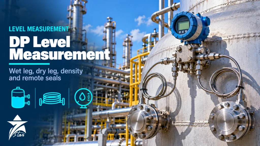
DP level measurement is still the default way to measure liquid level in closed pressure vessels, separators, boiler drums and columns, because a differential pressure transmitter is robust, well understood and easy to verify. Most field problems do not come from the transmitter itself but from the connection to the vessel: an impulse leg that slowly fills with condensate, a wet leg that evaporates in summer, a capillary that sits in the sun, or a range calculated with the wrong density. This guide explains how the measurement works, when to use a dry leg, a wet leg or remote seals, how to calculate the calibrated range, how to handle density changes and interface measurement, and which data to collect before you specify the instrument.
How Hydrostatic Level Measurement Works
A column of liquid exerts a pressure at its base equal to its height multiplied by its density and gravitational acceleration (P = ρ·g·h). In an open tank only one pressure is needed, because the surface is at atmospheric pressure and a gauge-pressure transmitter at the bottom reads the head directly. In a closed vessel the gas or vapour space above the liquid adds the same pressure to every point, so a single pressure reading cannot separate level from vessel pressure.
A DP transmitter solves this by connecting its high-pressure (HP) side to a bottom tap and its low-pressure (LP) side to a tap in the vapour space. The static pressure cancels and the transmitter reads only the liquid head between the taps. In practice engineers work in water column and specific gravity (SG): the head in mmH2O equals the liquid height in mm multiplied by the SG. That relationship drives every range calculation in this article.
The key consequence is that a DP transmitter measures head, not level.
Dry Leg, Wet Leg and Remote Seals Compared
The low-side connection decides how reliable the measurement will be over the years.
| Connection | How the LP side is filled | Best suited to | Main risk |
|---|---|---|---|
| Dry leg | Gas or non-condensing vapour | Tanks with dry blanket gas, non-condensing vapour space, low-volatility liquids | Condensate or carry-over slowly fills the leg and shifts the zero |
| Wet leg | Liquid of known density (process condensate or a seal liquid) | Condensing vapours, steam drums, many hydrocarbon vessels | Evaporation, leakage or temperature-driven density change of the leg fluid |
| Remote seals with capillary | Sealed fill fluid behind a diaphragm | Corrosive, viscous, plugging, hot or toxic service | Fill-fluid temperature effects, slower response, diaphragm damage |
| Electronic remote sensors | Two pressure sensors linked by a cable, no capillary | Tall vessels and columns where long capillaries would be slow or temperature sensitive | Accuracy suffers when the DP span is small compared with static pressure |
Dry leg in practice
A dry leg is the simplest configuration, but only if the leg stays dry. Slope the LP impulse line so any condensate drains back to the vessel, avoid pockets, and fit a condensate pot or drain valve where liquid could collect. If the vapour space contains anything that condenses at ambient temperature, the dry leg eventually becomes a partially filled wet leg of unknown height, producing a wandering zero that operators often blame on transmitter drift.
Wet leg in practice
A wet leg turns an unpredictable liquid head into a known, constant one. It is common on steam drums and condensing hydrocarbon vessels, where a condensate pot at the top tap keeps the leg full. Non-condensing services can use a filled leg with a stable seal liquid chosen so that it does not evaporate, freeze or react with the process. The leg must stay full and at a stable temperature; a leg that loses part of its height introduces an error equal to the lost height times the fill SG.
Remote seals, covered below, remove impulse lines altogether; our pressure transmitter selection guide explains how they fit into the wider transmitter choice.
Calculating LRV and URV: Worked Examples
Work through the calculation with the actual tap elevations from the vessel drawing, not the nominal tank height.
Dry leg, transmitter at the bottom tap
Taps are 4,000 mm apart, process SG is 0.85 and the transmitter sits at the same elevation as the bottom tap. At 0 % the head is 0 mmH2O. At 100 % it is 4,000 × 0.85 = 3,400 mmH2O, so the range is 0 to 3,400 mmH2O. If the transmitter is mounted 500 mm below the bottom tap, the liquid-filled HP impulse line adds 500 × 0.85 = 425 mmH2O at every level, so the range becomes 425 to 3,825 mmH2O. This positive offset is called zero suppression.
Wet leg, transmitter at the bottom tap
Same vessel, but the LP leg is filled over the full 4,000 mm with condensate of SG 1.0. At empty the transmitter sees 0 − 4,000 = −4,000 mmH2O. At full it sees 3,400 − 4,000 = −600 mmH2O. The range is −4,000 to −600 mmH2O. This negative offset is called zero elevation. The span (3,400 mmH2O) is unchanged; only the zero moves.
Remote seals
With a balanced pair of seals and capillaries filled with silicone of SG close to 0.94, the LP capillary between the two seal elevations behaves like a wet leg filled with that fluid. For 4,000 mm between seals the LRV is about −3,760 mmH2O and the URV about −360 mmH2O. Use the exact fill SG from the seal datasheet.
- Confirm the HP and LP connections before entering negative values; reversed legs are a common commissioning error.
- Record tap elevations, transmitter elevation and leg fluid SG on the loop sheet so the range can be re-checked later.
- After refilling a wet leg or replacing seals, verify the zero against a known level rather than trusting the old calibration.
Density Compensation
Because the transmitter measures head, any change in liquid density appears as a level change. The size of the error is easy to estimate: a 2 % drop in density gives a reading about 2 % below the true liquid height above the HP tap. In light hydrocarbons, LPG, hot water and solvent mixtures, temperature alone can move density by several percent over the operating range.
Common compensation methods are:
- Calculated compensation: measure liquid temperature, calculate density, and correct level in the DCS or PLC. This works when composition is stable.
- Direct density measurement: a second DP transmitter across two taps that are always submerged, with a known vertical spacing. Its reading divided by the spacing gives the liquid SG, which then corrects the main level reading.
- Hydrostatic tank gauging: several pressure sensors at known heights plus temperature allow level, density and mass to be calculated together, an approach used on storage tanks where inventory by mass matters.
- Boiler drum compensation: water and steam densities both change strongly with drum pressure, so drum level loops normally include pressure-based correction of the wet leg and process sides.
Interface Level by DP
When two immiscible liquids share a vessel, such as oil over water in a separator, a DP transmitter can measure the interface provided the vessel is always full above the upper tap. The reading moves between “all light liquid” and “all heavy liquid” between the taps, so the span equals the tap spacing multiplied by the SG difference.
Take taps 2,000 mm apart, oil SG 0.85 and water SG 1.00. The span is only 2,000 × 0.15 = 300 mmH2O. If the oil density drifts by 0.01 SG, the zero moves by 20 mmH2O, close to 7 % of span. That sensitivity is why interface by DP needs stable densities, wide tap spacing and attention to emulsion layers. Where the SG difference is small or the upper liquid varies, guided wave radar or a displacer often performs better; see our radar level transmitter selection guide for those alternatives.
Remote Seal Configurations for Level
Seal systems do not all behave the same way when ambient temperature changes. Choosing the configuration is as important as choosing the fill fluid.
- Balanced system: identical seals and capillary lengths on both sides. Fill-expansion effects on the two sides largely cancel, but the head of fill fluid in the LP capillary still changes as fill density changes with temperature.
- Tuned (asymmetric) system: the transmitter is direct-mounted to the lower seal and only the upper side uses a capillary. Several manufacturers offer this arrangement because the seal-volume effect and the capillary head effect partly offset each other, reducing the total temperature error.
- Electronic remote sensors: two pressure sensors connected electrically, with DP calculated digitally. They avoid capillary temperature errors and slow response on tall columns, but each sensor reads full static pressure, so accuracy falls when the level span is small relative to vessel pressure.
Keep capillaries as short as practical, route both together so they see the same temperature, and coil any surplus horizontally rather than letting it hang. Long capillaries increase response time, especially with viscous fills at low temperature.
Installation Guidelines
Good installation removes most long-term problems. These points apply to impulse-line systems; seal systems need the same attention to elevations and capillary routing.
- Locate the HP tap high enough to avoid sludge and sediment, remembering that level below the HP tap cannot be measured.
- Slope impulse lines continuously (about 1:12 is a common hook-up practice) so gas legs drain liquid back to the vessel and liquid legs vent gas back to the process.
- Fit a 3-valve or 5-valve manifold for zeroing and isolation, and close the equalising valve before putting the transmitter in service.
- Install the condensate pot for a wet leg at the elevation of the top tap.
- Keep both legs at the same temperature; any heat tracing or insulation must treat both legs equally.
- Provide vents and drains so legs can be refilled and checked without removing the transmitter.
GCC Site Conditions
Gulf installations add their own problems. Summer air temperature can approach 50 °C in parts of Oman and the wider GCC, and a capillary or wet leg in direct sun runs considerably hotter than the air. Uneven solar heating of the two sides produces a zero shift that follows the sun and appears as a daily wave on the level trend. Sunshades for transmitters and seals, shading for exposed capillaries and identical routing of both legs reduce the effect.
In sour gas and crude service, diaphragms and wetted parts must meet the H2S material requirements normally specified through NACE MR0175/ISO 15156. Where hydrogen is present, ask about gold-plated diaphragms, which several manufacturers offer to limit hydrogen permeation into the fill fluid. In coastal and offshore plants, specify 316 stainless or better for capillary armour and housings. Hazardous-area certification must match the area classification; zones, gas groups and temperature classes are covered in our hazardous area classification guide.
Common DP Level Measurement Mistakes
- Ranging from nominal tank height instead of actual tap elevations.
- Leaving a “dry” leg on a vessel with condensing vapour, then recalibrating every few months to chase the drift.
- Ordering remote seals without stating ambient temperature extremes, so the temperature error cannot be estimated.
- Mounting the transmitter above the lower seal in vacuum service.
Maintenance and Troubleshooting
Most DP level faults can be traced quickly with the manifold. Isolate both sides, open the equaliser and confirm the transmitter reads zero DP. If it does, the transmitter is healthy and the problem lies in the legs or the process. Then check each leg: a wet leg can be refilled and the reading compared with a gauge glass or manual dip; a dry leg can be drained to see whether liquid has accumulated.
For remote seals, a reading that changes with time of day points to temperature effects; a stuck or sluggish reading points to a damaged diaphragm, a crushed capillary or a plugged seal face. A seal that has lost fill fluid cannot be repaired in the field and normally needs factory refilling or replacement.
DP Level Measurement Specification Checklist
Collect this data before requesting a DP level transmitter or seal system:
- Vessel tag and drawing, with elevations of all taps and of the planned transmitter location.
- Process liquid(s) and SG at minimum and maximum operating temperature; for interface, both liquids.
- Operating and design pressure, including vacuum conditions.
- Process temperature range and ambient extremes, including solar exposure.
- Connection type: impulse lines with dry or wet leg, or remote seals with flange size, rating and facing.
- Wetted materials and any sour service, hydrogen or chloride requirements.
- Output and protocol (4–20 mA HART, fieldbus), hazardous-area certification and enclosure rating.
- Required accuracy and response time, plus the existing make and model if this is a replacement.
DP Level Transmitters We Supply
Wet and dry legs are one solution; remote seals and direct-mount seals are another. These examples cover both.
| Product | Type | Where it fits |
|---|---|---|
| Yokogawa EJX110A Differential Pressure Transmitter | DP transmitter | Wet-leg or dry-leg installations with impulse lines. |
| VEGA VEGADIF 85 Differential Pressure Transmitter | DP transmitter | Level and interface measurement in closed tanks. |
| Rosemount 3051SAL Liquid Level Transmitter | Level transmitter with seal | Tanks where a direct-mount seal avoids impulse lines altogether. |
| Rosemount 3051L Liquid Level Transmitter | Liquid level transmitter | Open and closed tanks with a flush flange connection. |
| ABB 266DRH / 2600T Differential Pressure Transmitter with Remote Seal | DP transmitter with remote seals | Closed vessels where capillaries replace wet legs. |
| Endress+Hauser Deltabar PMD78B Differential Pressure Transmitter | DP transmitter with diaphragm seals | Viscous, crystallising or hot media that would plug impulse lines. |
To configure a transmitter, send the vessel height, liquid density range, process temperature, pressure and the tap connections through our quote request form.
Sourcing DP Level Transmitters Through Seven Star LLC
Seven Star LLC supplies differential pressure transmitters, remote seal assemblies and manifolds on request for customers in Oman and the GCC, from manufacturers such as Emerson, Endress+Hauser, Yokogawa and ABB. We help with selection and with cross-checking model codes and part numbers against your datasheet; availability and lead time are confirmed at quotation. Browse our level instrumentation and pressure instrumentation categories for typical ranges.
Send us the instrument datasheet, a nameplate photo of the existing transmitter or your RFQ with tap elevations and process data, and we will prepare a matched quotation.
Frequently asked questions
What is the difference between a wet leg and a dry leg in DP level measurement?
A dry leg leaves the low-pressure impulse line filled with gas or vapour, so it only transmits the vessel's top pressure. A wet leg is deliberately filled with a liquid of known density, which adds a constant head to the low side. Use a dry leg when the vapour space will not condense; use a wet leg or remote seals when condensation would otherwise fill the low leg unpredictably.
Why does a wet leg give a negative calibration range?
The full wet leg pushes on the low side with a head equal to its height times its specific gravity, and that head is usually larger than the process head on the high side. The transmitter therefore sees a negative differential pressure at empty and a smaller negative value at full. This is called zero elevation and it is normal; LRV and URV are simply set to those negative values.
Does the transmitter mounting height matter with balanced remote seals?
For a balanced two-capillary system filled with the same fluid, the fixed offset depends on the vertical distance between the two seals, not on where the transmitter sits. Mounting height does matter in vacuum service, where the transmitter is normally installed at or below the lower seal so the fill fluid stays above its vapour pressure. Always follow the seal manufacturer's installation limits.
How accurate is DP interface level measurement?
Accuracy depends mostly on the density difference between the two liquids. The calibrated span equals the tap spacing multiplied by the SG difference, so a small difference gives a small span and any density drift becomes a large percentage error. When the SG difference is small, compare the DP option against guided wave radar or a displacer before committing.
How do I compensate DP level for density changes?
If density varies with temperature but composition is stable, calculate density from a measured temperature and correct the level in the control system. If composition also varies, install a second DP measurement across a fixed, always-submerged tap spacing to measure density directly. Hydrostatic tank gauging extends this idea with several pressure sensors to compute level, density and mass.
When should I replace impulse lines with remote seals for level?
Remote seals make sense when the process is corrosive, viscous, crystallising, solids-laden, very hot or toxic, or when a wet leg would boil off or freeze. They also remove the plugging and leak points of long impulse lines. The trade-offs are higher temperature sensitivity, slower response with long capillaries and a higher initial cost.
Was this guide helpful?One click helps us write better guides for engineers.
Thank you! Glad it helped. Need this equipment for your project? Request a quotation
Thank you. We will use this to improve the guide.