
- Vibration Monitoring
- PLC & I/O Cards
- Industrial Communications
- Controllers & Data Acquisition
- Automation Accessories
- AC Drives
- Isolator & Barrier
- Industrial Computers
- Encoders
- Automation Software
- HMI Displays
- Motor Soft Starters
- Servo Drives
- CCTV & Security
- Machine Vision
- Pneumatic Cylinders
- Robotics
- Safety Switches & Guard Locking
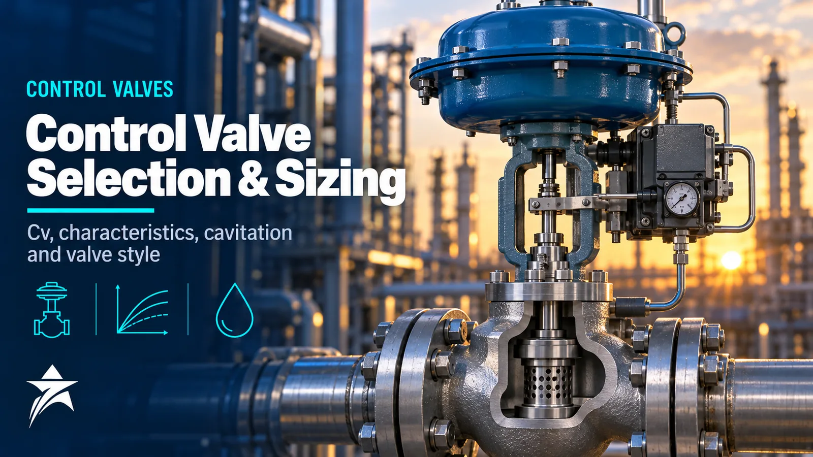
Control Valve Selection and Sizing: Cv, Characteristics, Cavitation, Noise and Choosing the Right Valve Style
The control valve is the final element in most control loops and frequently the weakest. An oversized valve controls near its seat and hunts; an undersized one runs out of capacity at maximum flow; a valve with the wrong trim cavitates, erodes or exceeds noise limits within months. Good control valve selection is not a catalogue exercise but a sequence of engineering checks: capacity across the full operating range, characteristic, pressure drop behaviour, noise, shutoff, materials and actuation. This guide works through that sequence for engineers who specify, review or replace valves.
Flow Coefficients: Cv and Kv
Valve capacity is expressed as a flow coefficient. Cv is the flow of water in US gallons per minute at 60 °F that passes through the valve with a pressure drop of 1 psi. Kv is the flow of water in m³/h at a pressure drop of 1 bar. The conversion is Kv ≈ 0.865 Cv, or Cv ≈ 1.156 Kv.
For a non-choked liquid, the basic relationship is:
Kv = Q × √(SG / ΔP)
with Q in m³/h, SG the specific gravity relative to water and ΔP in bar. Gas and steam sizing add an expansion factor and a pressure-drop ratio term, and all real sizing must also apply piping geometry factors where reducers are fitted.
Sizing equations are standardised in IEC 60534-2-1 and ANSI/ISA-75.01.01, which are technically aligned. Manufacturers’ sizing programs implement these equations with their own valve-specific factors, so final sizing should always be done with the manufacturer’s data for the exact valve and trim.
Sizing Across the Operating Range
Size the valve at minimum, normal and maximum flow, each with its own upstream pressure, downstream pressure and temperature. A single design point hides the problems that appear at the extremes.
Common practice targets include:
- Maximum flow at roughly 70 to 80% of travel for equal percentage trims, leaving margin without excessive oversizing.
- Minimum flow at no less than about 10 to 20% of travel, to keep the plug away from the seat where control is poor and erosion is concentrated.
- Normal flow in the middle of the range where the loop spends most of its time.
Avoid stacking safety factors. If the process engineer has already added margin to maximum flow, adding another 25% at the valve leads to a valve that runs at 15% travel in normal service. The pressure drop used for sizing should be the drop actually available at each flow from the system curve, not a single assumed figure.
Inherent and Installed Characteristics
The inherent characteristic is the relationship between travel and flow at constant pressure drop:
| Characteristic | Behaviour | Typical use |
|---|---|---|
| Linear | Equal flow increments per unit travel | Systems where valve pressure drop stays roughly constant, such as level control with a large fixed head |
| Equal percentage | Equal travel increments give equal percentage changes of existing flow | Most pressure and flow loops, particularly where the valve takes a small share of total system loss |
| Quick opening | Most of the capacity in the first part of travel | On-off and some relief duties, not continuous throttling |
In a real system the valve’s share of total pressure drop changes with flow: as flow rises, pipe and equipment losses grow and the drop across the valve falls. This distorts the inherent characteristic into the installed characteristic. An equal percentage valve in a system where it has a low share of total pressure drop tends to install closer to linear, giving roughly constant loop gain. That is why equal percentage is the default for most process applications. A linear valve in the same system would have high gain at low flow and low gain at high flow.
Valve Styles
| Style | Strengths | Limitations | Typical services |
|---|---|---|---|
| Globe, cage-guided | Wide trim choice, including anti-cavitation and low-noise cages; good rangeability; balanced designs for high ΔP | Higher cost and weight in large sizes; cage can foul in dirty service | General process control, high-pressure drop, steam, gas letdown |
| Globe, top- or post-guided | Tolerates dirty and viscous fluids better than tight cage clearances | Less trim flexibility for severe service | Dirty liquids, slurries, heavy oil |
| Angle valve | Flow path suits erosive, flashing and high-ΔP liquids; erosion directed away from the body | Piping arrangement | Produced water, sand-laden fluids, letdown with flashing |
| Segmented ball (V-ball) | High capacity, good rangeability, shearing action on fibrous or dirty fluids | Lower pressure recovery factor so more prone to cavitation and choked flow | Slurries, pulp-type and dirty services, large flows |
| Eccentric rotary plug | Robust, good for erosive and viscous fluids, tight shutoff | Moderate capacity | Dirty hydrocarbons, slurries |
| High-performance butterfly | Compact, economical in large sizes | Limited high-ΔP capability; noise and cavitation limits | Large water, cooling water, low-ΔP gas |
| Triple-offset butterfly | Metal-seated tight shutoff, high temperature | Throttling range more limited than globe | Isolation-plus-control, high-temperature service |
Examples include the Fisher easy-e EZ cage-guided globe valve, the Fisher HPT high-pressure globe, the Samson 3241 globe valve, the Fisher Vee-Ball V150 segmented ball, the Neles R-Series segment valve, the Fisher CV500 eccentric plug and the Fisher 8560 high-performance butterfly.
Cavitation and Flashing
As liquid accelerates through the restriction, pressure reaches a minimum at the vena contracta and then partly recovers downstream. If the vena contracta pressure falls below the vapour pressure, vapour bubbles form. If downstream pressure recovers above vapour pressure, the bubbles collapse: cavitation, with noise, vibration and pitting damage to trim and body. If downstream pressure stays below vapour pressure, the fluid leaves as a two-phase mixture: flashing, which causes erosion from high-velocity droplets.
The liquid pressure recovery factor FL describes how much pressure a valve recovers. High-recovery valves, with low FL, such as many ball and butterfly designs, are more prone to cavitation than low-recovery globe valves. IEC 60534-2-1 uses FL to estimate the onset of choked flow:
ΔP choked = FL² × (P1 − FF × Pv)
where FF is the liquid critical pressure ratio factor. If the sizing ΔP exceeds this, flow is choked and the trim is cavitating or flashing heavily. Solutions include anti-cavitation trims that stage the pressure drop through multiple paths so local pressures stay above vapour pressure, such as the Masoneilan 41005 with VRT trim; hardened trim materials; angle bodies for flashing service; and relocating the valve so downstream pressure is higher. Flashing cannot be prevented by trim; the design goal is to manage it with materials and geometry.
Noise
Aerodynamic noise from gas and steam letdown is the most common noise problem. It is predicted with IEC 60534-8-3, and hydrodynamic noise from liquids with IEC 60534-8-4. Many specifications set a limit of around 85 dBA at 1 m downstream and 1 m from the pipe surface, but follow the project or site specification.
Noise reduction works at source or along the path:
- Source treatment: multi-hole, multi-stage low-noise cages that reduce jet velocity and shift frequency upward.
- Path treatment: downstream diffusers, silencers or cartridges such as the Masoneilan Lo-dB cartridge, heavier pipe schedule and acoustic insulation.
High noise is also a mechanical issue. Vibration at high sound levels can fatigue small-bore connections, instrument tubing and thermowells downstream of the valve.
Shutoff, Materials and Emissions
Seat leakage classes are defined by ANSI/FCI 70-2 (and IEC 60534-4). Class IV allows 0.01% of rated capacity and is typical for metal-seated balanced globe valves. Class V is a much tighter metal-seat class. Class VI is soft-seat tight shutoff measured in bubbles per minute. Specify only the class the process needs; tighter classes add cost and may restrict trim options.
For sour service, wetted metallic materials must comply with NACE MR0175/ISO 15156 in production, or NACE MR0103 where refinery practice applies. Duplex and super duplex stainless steels are common for seawater and brine. For erosive service, specify hardened trims such as stellite or tungsten carbide.
Fugitive emissions requirements are increasingly specified by ISO 15848-1, which classifies stem seal tightness and endurance. Packing selection must balance tightness against friction, since high-friction packing degrades positioner performance.
Actuators and Positioners
Spring-diaphragm actuators are simple, reliable and provide inherent fail-safe action; they suit most globe and rotary valves within their thrust range. Piston actuators provide higher thrust and stiffness for high-ΔP valves and large rotary valves, with springs or volume tanks for fail-safe action. Size the actuator for the maximum shutoff pressure, packing friction and the seat load required for the leakage class, with margin.
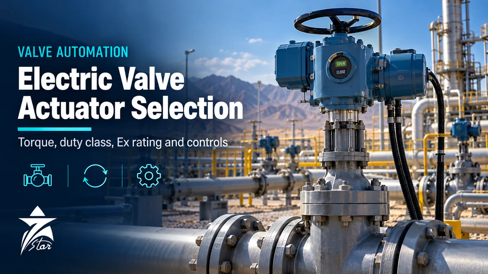
A digital positioner improves accuracy and provides diagnostics for valve signature and friction tracking; see our valve positioner category. Where pneumatic supply is unavailable, an electric actuator may be appropriate; our electric valve actuator selection guide compares the two approaches.
Oman Service Conditions
Several local conditions drive valve selection:
- Produced water and crude in many fields carry sand. Angle bodies, hardened trim, reduced velocity and erosion-resistant materials extend trim life.
- Desalination plants combine high pressure on reverse osmosis feed with seawater and brine chemistry; duplex and super duplex bodies and trims, plus cavitation checks on brine and recirculation valves, are typical.
- Steam conditioning in power and process plants uses dedicated designs such as the Masoneilan 84000 SteamForm.
- Solar heating raises actuator and positioner temperatures well above ambient. Check elastomer diaphragm and soft-seat temperature limits, and shade positioners where possible.
- Dust and sand affect stem packing and positioner exhausts; use stem boots where offered and protect vents.
Common Mistakes
- Sizing at one design point and ignoring minimum flow.
- Adding margin on margin, producing a valve that controls near the seat.
- Selecting a high-recovery rotary valve for a high-ΔP liquid without a cavitation check.
- Specifying Class VI shutoff where Class IV is sufficient.
- Undersizing the actuator for shutoff with the packing friction actually installed.
- Overlooking noise until commissioning.
Control Valve Specification Checklist
- Process data sheet in ISA-75 style with minimum, normal and maximum conditions.
- Fluid properties: vapour pressure, critical pressure, density, viscosity, solids content.
- Calculated Cv at each case and travel at each case.
- Inherent characteristic justified against installed behaviour.
- Cavitation, flashing and choked-flow checks.
- Predicted noise against the specified limit.
- Shutoff class and direction.
- Body and trim materials, NACE compliance, hardened trim if needed.
- Packing and ISO 15848 class if required.
- Actuator type, fail action and sizing margin.
- Positioner, accessories and air supply.
- End connections, face-to-face and pressure rating.
Sourcing Control Valves Through Seven Star LLC
Seven Star LLC supplies control valves, trims and actuation equipment from established manufacturers for oil and gas, power and desalination plants in Oman. Browse the control valves category and send us your process data sheet so we can propose suitable options.
Send Seven Star LLC your control valve data sheet, and we will help you source a valve sized and specified for your service.
Was this guide helpful?One click helps us write better guides for engineers.
Thank you! Glad it helped. Need this equipment for your project? Request a quotation
Thank you. We will use this to improve the guide.
Need a Quotation for Your Project?
Seven Star LLC supplies the industrial equipment covered in this article to customers across Oman and the GCC. Send us the part numbers, models or a short description with quantities, and our sales team will reply with a formal quotation.
- Genuine OEM products
- Supply across Oman & the GCC
- Formal quotation from our sales team
Free, no-obligation quotation · takes about 1 minute
Other enquiries: [email protected] · WhatsApp
More Blog




Frequently Asked Questions
Cv is the flow of water in US gallons per minute through a valve at 1 psi pressure drop, while Kv is the flow of water in cubic metres per hour at 1 bar pressure drop. They describe the same capacity in different units, with Kv approximately equal to 0.865 times Cv.
In most systems the valve takes a decreasing share of total pressure drop as flow increases. An equal percentage valve in that situation installs closer to linear, giving more consistent loop gain across the operating range.
Cavitation occurs when the pressure at the vena contracta falls below the liquid vapour pressure and then recovers above it downstream, causing vapour bubbles to collapse. It produces noise, vibration and pitting, and is controlled with anti-cavitation trims, low-recovery valve styles or a different pressure drop arrangement.
Under ANSI/FCI 70-2, Class IV allows leakage of 0.01% of rated capacity and is typical for metal-seated valves. Class VI is soft-seated tight shutoff measured in bubbles per minute, used where very low leakage is required.
Common practice is roughly 70 to 80% of travel at maximum flow for equal percentage trims, with minimum flow no lower than about 10 to 20%. Project specifications may set different targets, and sizing should be checked across all operating cases.
Many specifications set a limit of about 85 dBA measured 1 m downstream and 1 m from the pipe surface. The actual limit is set by the project or site specification, and noise is predicted with IEC 60534-8-3 for gas and IEC 60534-8-4 for liquids.