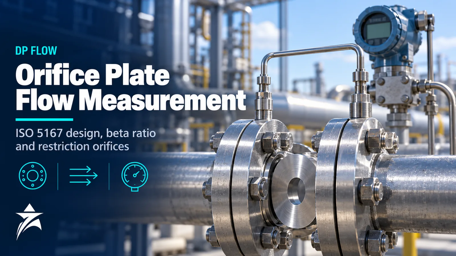
Orifice Plate Flow Measurement: ISO 5167 Design, Beta Ratio, Tapping Types and Restriction Orifices
The orifice plate is the oldest and most thoroughly standardised flow element in process industry. It needs no flow calibration when built and installed to the standard, it is available in almost any line size and material, and its behaviour is documented by decades of test data. That reliability depends entirely on geometry and installation. A rounded edge, a short straight run or a plate installed backwards can introduce errors of several percent without any alarm. This guide covers orifice plate flow measurement from the equations through ISO 5167 design rules, tapping types, installation and inspection, and explains how a restriction orifice differs from a metering orifice.
The Principle
An orifice plate is a thin plate with a precisely machined hole, clamped between flanges. As flow accelerates through the bore, static pressure falls. The pressure difference between upstream and downstream tappings is related to flow through Bernoulli’s equation and continuity, corrected by an empirically determined discharge coefficient:
qm = C / √(1 − β⁴) × ε × (π/4) × d² × √(2 × Δp × ρ1)
where qm is mass flow, C the discharge coefficient, β the diameter ratio d/D, ε the expansibility factor (equal to 1 for liquids), d the orifice bore at operating temperature, Δp the differential pressure and ρ1 the upstream density.
Two consequences follow. First, flow is proportional to the square root of DP. Doubling flow quadruples DP, so a DP transmitter with 10:1 usable range gives only about 3:1 flow turndown, and a practical range is usually quoted as about 3:1 to 4:1 per transmitter. Wider ranges use two or three transmitters with staggered spans, switched in the flow computer or DCS. Second, density appears directly in the equation, so gas measurement needs pressure and temperature compensation and, for natural gas, a compressibility calculation.
Standards: ISO 5167 and AGA 3
ISO 5167-1 sets general principles, and ISO 5167-2 covers orifice plates: geometry, tappings, installation, the discharge coefficient equation and uncertainty. The discharge coefficient is calculated with the Reader-Harris/Gallagher equation, which accounts for beta ratio, Reynolds number and tapping position. For natural gas, AGA Report No. 3 is widely used, particularly with flange taps, and its current editions also use the Reader-Harris/Gallagher equation.
ISO 5167-2 defines limits of use, including minimum and maximum pipe diameter, minimum bore, Reynolds number limits and a permitted beta range of 0.1 to 0.75. Within those limits, the uncertainty of the discharge coefficient is typically around 0.5% for beta up to about 0.6, increasing at higher beta. Total flow uncertainty also includes DP, density and dimensional uncertainties, so a well-installed plate typically achieves around 0.5 to 1% of flow overall when instruments are selected and calibrated well. Outside the standard’s limits, there is no basis for claiming the standard uncertainty.
Beta Ratio and Plate Geometry
The beta ratio is the main design variable. Most designers stay well inside the ISO limits, typically choosing beta somewhere in the 0.2 to 0.7 region. Low beta gives high DP for a given flow, which improves resolution but increases pressure loss. High beta reduces pressure loss but increases sensitivity to upstream flow disturbances and lengthens straight-run requirements.
Geometric requirements in ISO 5167-2 include:
- A sharp, square upstream edge free of burrs, wire edges and visible rounding.
- An edge (bore) thickness and a total plate thickness within limits set relative to pipe diameter.
- A bevel on the downstream side, normally at 45° with a tolerance, when the plate is thicker than the allowed bore thickness.
- Flatness and parallelism of the faces.
- A smooth upstream face.
Permanent pressure loss is a significant fraction of the DP. It can be estimated approximately as (1 − β^1.9) × Δp, so a plate with beta 0.6 permanently loses roughly 60% of its DP. On large compressor or pump systems this is a real energy cost and a reason to consider low-loss elements.
Tapping Types
ISO 5167-2 recognises three tapping arrangements. The discharge coefficient equation includes terms for each, so the calculation must use the tapping type actually installed.
| Tapping type | Tap locations | Typical application | Notes |
|---|---|---|---|
| Flange taps | 25.4 mm (1 inch) upstream and downstream of the plate faces, drilled through orifice flanges | Most common in oil and gas, including natural gas to AGA 3 | Requires orifice flanges; simple plate change |
| Corner taps | At the plate faces, often via annular chambers or carrier rings | Smaller line sizes and European practice | Carrier rings simplify installation and centring |
| D and D/2 taps | One pipe diameter upstream and half a diameter downstream | Larger lines and older installations | Taps in the pipe wall, independent of flanges |
Orifice flange assemblies such as the ABB FPD160 provide flange taps and jacking screws for plate removal. Carrier assemblies such as the ABB FPD175 with integral manifold package the plate, corner taps and manifold into a single unit. Standard plates, such as the ABB FPD150 orifice plates, are made to ISO 5167 geometry.
Straight Lengths and Flow Conditioning
The discharge coefficient equation assumes a fully developed, swirl-free velocity profile. ISO 5167-2 tabulates minimum upstream and downstream straight lengths for different fittings and beta ratios. Requirements range from roughly 10D for benign fittings at low beta to well over 40D for combinations such as two bends in different planes at high beta. Downstream requirements are shorter. The standard also allows reduced lengths with an added uncertainty, and with qualified flow conditioners.
Where plot space is limited, which is common on compact skids, use a flow conditioner that has been qualified to the standard’s compliance tests, or reduce beta. Do not assume that a short run will “average out”; swirl from out-of-plane bends can persist for long distances and bias the measurement.
Compact, Integral and Multivariable Solutions
For small lines, an integral orifice places a small precision bore inside a body that bolts directly to the DP transmitter, as in the ABB 1330L integral orifice flow element. This suits flows too small for a conventional plate, such as chemical injection, purge or utility flows. Compact orifice flowmeters integrate the primary element and transmitter into one assembly, such as the ABB OriMaster FPD500 and the IOMaster FPD510.
For compensated gas and steam flow, a multivariable transmitter such as the ABB 267CS measures DP, static pressure and process temperature in one device. For fiscal gas metering, the calculation normally sits in a dedicated flow computer with AGA 3 or ISO 5167 calculations and an audit trail. In gas metering, dual-chamber orifice fittings are often used so the plate can be withdrawn for inspection without depressurising the line.
DP Transmitter and Impulse Line Installation
Many orifice measurement problems are impulse line problems. The rules follow from keeping the lines filled with a single phase:
- Gas service: mount the transmitter above the taps, with lines sloping continuously up to the transmitter so liquids drain back to the pipe. Taps on the top or upper side of the pipe.
- Liquid service: mount the transmitter below the taps, with lines sloping down so gas vents back to the pipe. Taps on the side of the pipe, not the bottom (sediment) or top (gas).
- Steam service: transmitter below the taps, with condensate-filled legs of equal height and, where used, condensate pots at the same elevation.
- Keep both impulse lines the same length and temperature to avoid unequal head errors, and use a 3- or 5-valve manifold for isolation, equalisation and zero checks.
A high-performance DP transmitter such as the Rosemount 3051S improves accuracy at the low end of the flow range, where DP is small. For transmitter selection and range considerations, see our pressure transmitter selection guide.
Metering Orifice Versus Restriction Orifice
A restriction orifice (RO) looks similar but has a different purpose: it limits flow or creates a fixed pressure drop, for example in minimum-flow bypass lines, purge supplies, depressurisation lines and blowdown. It is not designed for measurement and is usually sized with different correlations from ISO 5167.
| Aspect | Metering orifice | Restriction orifice |
|---|---|---|
| Purpose | Measure flow from DP | Limit flow or drop pressure |
| Design basis | ISO 5167-2 or AGA 3 | Vendor or engineering correlations for choked and unchoked flow |
| DP | Usually modest, set for transmitter range | Often large, sometimes most of the line pressure |
| Plate | Thin plate with sharp edge | Often thicker plates; multi-stage designs for high ΔP |
| Key risks | Edge wear, deposits, installation errors | Choking, noise, vibration, cavitation and erosion |
In gas service, once the downstream-to-upstream pressure ratio falls below the critical ratio, flow becomes choked and no longer increases with lower downstream pressure. That property is used deliberately to limit maximum flow, but a single-stage RO across a large pressure drop generates high noise and vibration. Multi-stage restriction orifices, such as assemblies built around the ABB FPD190 restriction orifice plate, split the drop into several stages. In liquid service, multi-staging keeps pressure above vapour pressure at each stage and limits cavitation damage.
Plates sometimes have small drain or vent holes to pass condensate in gas or gas in liquids. These holes add flow that the standard equation does not cover; avoid them in fiscal service and account for them where unavoidable.
Primary Element Comparison
| Element | Pressure loss | Straight run | Typical fit |
|---|---|---|---|
| Orifice plate | High | Long | General service, gas metering, wide size range |
| Venturi tube | Low | Moderate | Large water and gas lines where energy loss matters |
| Wedge element | Moderate | Moderate | Slurries, viscous and dirty liquids |
| Cone-type element | Moderate | Short | Space-limited installations and wet gas |
Inspection, Oman Conditions and Common Mistakes
Plate inspection should check edge sharpness, flatness, bore diameter, surface damage and deposits, plus that the plate is installed with the sharp edge facing upstream. Produced fluids in many Omani fields carry sand, which erodes and rounds the upstream edge. A rounded edge increases the discharge coefficient, so the meter under-reads with no alarm. Waxy crude and condensate leave deposits that shift readings. Set inspection intervals by service: tighter for sand-laden or dirty flows, longer for clean dry gas.
Common mistakes include:
- Plates installed backwards after maintenance.
- Wrong bore or beta entered in the flow computer after a plate change.
- Gaskets protruding into the bore.
- Gas lines with liquid traps in impulse lines, or liquid lines with trapped gas.
- Ignoring the square-root turndown limit and expecting good accuracy at 10% flow.
- Using a restriction orifice reading as a flow measurement.
Orifice Metering Checklist
- Process data at minimum, normal and maximum flow, with composition.
- Design standard: ISO 5167-2 or AGA 3, and the edition used.
- Beta ratio within limits and DP suited to transmitter range.
- Tapping type and matching flanges or carrier.
- Plate material, thickness and bevel for pressure and temperature.
- Straight lengths or qualified flow conditioner.
- Transmitter selection, single or stacked, and manifold type.
- Impulse line routing for the fluid phase.
- Compensation: multivariable transmitter or flow computer.
- Inspection interval and plate change method.
Sourcing Orifice Assemblies Through Seven Star LLC
Seven Star LLC supplies orifice plates, flange and carrier assemblies, restriction orifices and DP transmitters for metering and utility applications in Oman. Browse our flowmeters category or the ABB brand page, and send your process data sheet for a matched proposal.
Send Seven Star LLC your process data and line details, and we will help you source the right orifice assembly and transmitter.
Need a Quotation for Your Project?
- Genuine OEM products
- Supply across Oman & the GCC
- Formal quotation from our sales team
Free, no-obligation quotation · takes about 1 minute
Other enquiries: [email protected] · WhatsApp
More Blog