- Automation & ControlView all 1,920 products
- AC Drives
- PLC & I/O Cards
- Industrial Communications
- Vibration Monitoring
- Automation Accessories
- Controllers & Data Acquisition
- Isolator & Barrier
- CCTV & Security
- Safety Switches & Guard Locking
- Encoders
- HMI Displays
- Industrial Computers
- Motor Soft Starters
- Servo Drives
- Pneumatic Cylinders
- Machine Vision
- Automation Software
- Robotics
















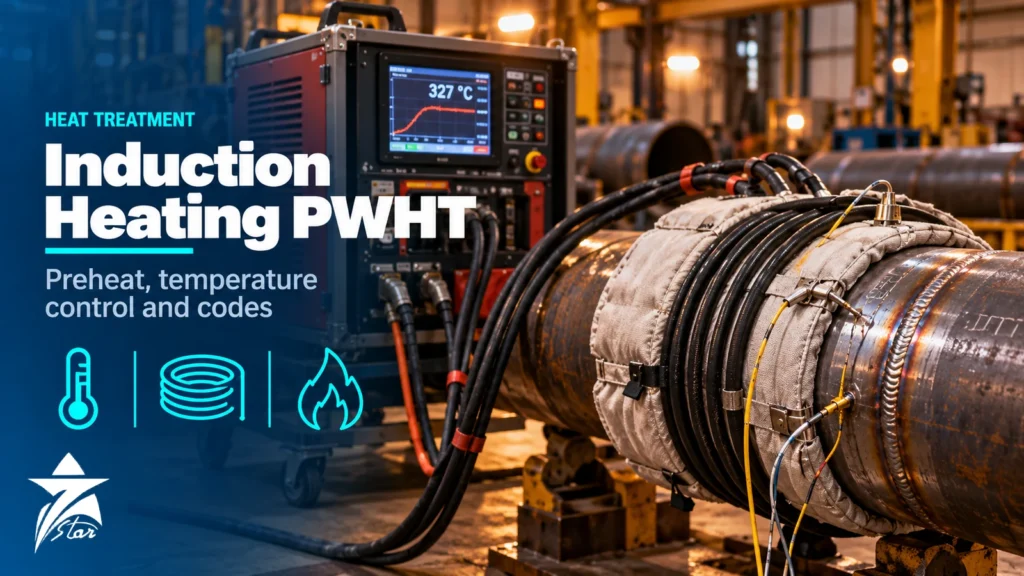
Preheat and post-weld heat treatment decide whether a weld in thick carbon steel, chrome-moly or sour-service piping leaves the shop sound or cracks days later. For decades most site crews used ceramic resistance pads or gas torches, but induction heating PWHT and induction preheating have become the default on many pipeline spreads and plant shutdowns because they heat faster, more evenly and with far less set-up labour. This guide explains how induction heating works on a weld joint, how it compares with resistance and flame heating, what the main codes actually require for temperature, rate and soak band, how temperature is measured and recorded, and which data to collect before you specify or buy a system.
Why Preheat and PWHT Are Specified at All
Preheat and PWHT solve different problems, so it helps to keep them separate when reading a welding procedure specification (WPS).
- Preheat slows the cooling rate of the weld and heat-affected zone (HAZ), reducing hard martensitic microstructures, and gives diffusible hydrogen time to escape. Its main target is hydrogen-induced cold cracking in hardenable steels and thick sections.
- Interpass temperature sets the minimum (and often a maximum) temperature between runs, so the joint neither cools below preheat nor overheats and loses toughness.
- Post-heat or hydrogen bake-out holds the joint at a moderate temperature immediately after welding to drive out hydrogen before the joint cools, often used where PWHT is delayed.
- PWHT heats the completed joint to a sub-critical temperature, holds it and cools it under control. It relaxes residual stress, tempers hard HAZ structures and improves resistance to stress corrosion cracking, which is why sour-service and caustic-service specifications lean on it heavily.
Low-hydrogen practice starts before any heater is switched on: properly stored and re-dried consumables from electrode drying ovens do more to prevent hydrogen cracking than extra preheat applied to wet electrodes.
How Induction Heating Works on a Weld Joint
An induction system consists of a power source, a coil (flexible cable or rigid fixture) wrapped around insulation on the pipe, and a temperature controller. The power source drives alternating current through the coil, typically at medium frequency in the kilohertz range. The alternating magnetic field induces eddy currents in the pipe wall, and the steel heats from within rather than from a hot surface touching it. Below the Curie temperature, carbon steel is magnetic and couples strongly; above it (roughly 770 °C for plain carbon steel) heating efficiency falls, which is one reason PWHT temperatures well below that point are easy to hold with induction.
Two coil types dominate field work:
- Air-cooled cables and blankets are light and fast to fit, and they are normally used for preheat and interpass maintenance at moderate temperatures.
- Liquid-cooled cables carry higher current and survive the temperatures needed for PWHT when wrapped over suitable high-temperature insulation. The coolant circuit becomes part of the equipment you must specify and maintain.
Because the heat is generated inside the wall, the through-thickness temperature gradient is lower than with surface heaters, and the joint can be welded with the coil left in place on many preheat set-ups, since the coil itself stays relatively cool.
Induction vs Resistance vs Flame Heating Compared
| Factor | Induction | Resistance (ceramic pads) | Flame (torch or ring burner) |
|---|---|---|---|
| Heat source | Eddy currents inside the steel | Hot elements conduct and radiate into the surface | Combustion gas on the surface |
| Heating speed | Fast; limited mainly by code rate limits | Moderate; pads must heat first | Fast locally but uneven |
| Uniformity around the circumference | Good with correct coil spacing | Good if pads and insulation are well fitted | Poor; hot spots and cold sides common |
| Suitability for PWHT | Yes, with liquid-cooled coils | Yes, the traditional site method | Generally limited to preheat; controlled PWHT is difficult |
| Set-up labour | Low; wrap insulation and cable | Higher; pads, wiring, banding | Lowest, but needs constant attention |
| Welder comfort | Coil stays relatively cool | Hot pads near the welder | Open flame and heat near the joint |
| Consumables | Insulation; occasional cable damage | Pads wear and burn out | Fuel gas |
| Capital cost | Highest | Moderate | Lowest |
| Typical best fit | Repetitive pipeline and plant joints, thick walls, tight schedules | Mixed work, complex geometries, fleets already owned | Small, thin or occasional preheat jobs where the WPS allows |
Resistance heating is still the most flexible choice for odd geometries such as valve bodies, nozzles and branch connections, because pads can be arranged freely. Induction pays back where many similar joints must be heated to the same cycle, where wall thickness is high and where a site schedule depends on cutting heat-up time.
What the Codes Require: Temperature, Hold, Rates and Soak Band
The governing code, the material P-Number and the project specification set the numbers, not the heating method. A few reference points engineers meet most often:
- ASME B31.3 (process piping) lists PWHT requirements in Table 331.1.1. For P-No. 1 carbon steel the temperature range is 595–650 °C, and PWHT becomes mandatory above a nominal thickness of 19 mm in recent editions, with exemptions and additional requirements in the notes and in the owner’s specification.
- ASME Section VIII Division 1 (UCS-56) sets a minimum holding temperature of 595 °C for P-No. 1 material, with a hold of 1 hour per 25 mm of thickness up to 50 mm. Above 425 °C, the heating rate must not exceed 222 °C/h divided by the thickness in inches, capped at 222 °C/h and never required to be less than 56 °C/h. Cooling above 425 °C is limited in the same way, at 278 °C/h divided by thickness, capped at 278 °C/h.
- ASME Section VIII UW-40 covers local PWHT and defines a minimum soak band: the weld plus, on each side, the lesser of the base metal thickness or 50 mm.
- AWS D10.10, the recommended practice for local heating of welds in piping and tubing, gives guidance on heated band width, gradient control band width, insulation and thermocouple placement, and it applies equally to induction and resistance methods.
- ISO 17663 sets quality requirements for heat treatment in connection with welding, and ISO 13916 covers how preheat, interpass and preheat maintenance temperatures are measured.
- Sour service under NACE MR0175 / ISO 15156 limits hardness of carbon steel welds, so PWHT may be required to bring the HAZ within limits even where the construction code would not demand it.
Always work from the current edition of the code and the client specification; values above are given to show the type of requirement, and editions do change thickness thresholds and notes.
Soak Band, Heated Band and Gradient Control
Local PWHT fails more often from geometry than from temperature. Three zones must be designed, whatever the heat source:
- Soak band: the weld, HAZ and adjacent base metal that must reach and hold the specified temperature range.
- Heated band: the wider area covered by the coil or pads. It must be wide enough that the soak band stays within tolerance at its edges, not just at the weld centreline.
- Gradient control band: insulation beyond the heated band that limits the axial temperature drop, keeping induced stresses low and protecting nearby components.
With induction, heated band width is set by coil length and turn spacing. Too few turns, uneven spacing or a coil that slips during the cycle produces cool spots at the band edges. On large diameters, the bottom of a horizontal pipe often runs cooler because of convection inside the bore, so closing pipe ends to stop chimney draft is a simple but frequently forgotten step.
Temperature Measurement, Control and Records
A heat treatment is only as good as its thermocouples. Field practice relies on Type K thermocouples attached directly to the pipe surface, usually by capacitor-discharge welding of the wires, connected to a multi-channel controller and a recorder that produces the time-temperature chart for the quality dossier. For background on sensor types, tolerances and extension cable, see our guide to RTD vs thermocouple selection.
- Place the control thermocouple in the soak band where it represents the joint, not under the coil turns where it may read high.
- Add monitoring thermocouples around the circumference; the number rises with pipe diameter, and on horizontal pipe one should sit at the bottom position.
- Place at least one at the edge of the soak band to prove the full band reached temperature.
- Check that the recorder chart shows time, all channels, heating and cooling rates and hold duration in a form the inspector can verify against the WPS.
- Verify the controller and recorder against a calibrated source before the job; spare temperature instrumentation and thermocouple wire should be on hand, because one failed channel can void a cycle.
Sizing and Specifying an Induction Heating System
Suppliers can only propose a suitable power source and coil set when they know the job. Collect the following before requesting a quotation:
- Material grades and P-Numbers, outside diameters and wall thicknesses (the largest and thickest joint drives power).
- Required process: preheat only, preheat plus interpass, hydrogen bake-out, or full PWHT.
- Target temperatures, holding times, heating and cooling rate limits and soak band from the WPS.
- Number of joints per day and whether several joints must be heated simultaneously.
- Joint geometry: butt welds, branch connections, flanges, valves, vessel nozzles or longitudinal seams.
- Available site power (voltage, phase, frequency, generator capacity) and ambient conditions.
- Coil type preference (air-cooled for preheat, liquid-cooled for PWHT), cable lengths and insulation stock.
- Recording requirements: number of channels, digital data export and chart format for the client.
Seven Star LLC lists power sources, cables and accessories under induction heating and preheating equipment, alongside the wider range of welding equipment used on the same projects.
Common Mistakes on Site
- Measuring preheat with a contact probe on the bevel face only, instead of at the location defined by the procedure.
- Letting a joint cool below preheat between passes during breaks or shift changes, then resuming without re-heating.
- Using a control thermocouple under the coil, producing a chart that looks perfect while the soak band edges stayed below temperature.
- Insufficient insulation width, giving steep axial gradients and distortion of thin-wall adjacent spools.
- Leaving pipe ends open so internal air flow cools the bottom of the joint.
- Heating near valves, instruments or flange gaskets without checking their temperature limits.
- Assuming PWHT can be skipped because a hardness reading looks acceptable, when the code or sour-service specification makes it mandatory.
GCC Site Conditions: Heat, Dust and Power Supply
Desert and coastal sites in Oman and the wider GCC add their own constraints. Induction power sources are air- or liquid-cooled electronics, and enclosure temperatures under direct sun at ambient temperatures near 50 °C can push them into thermal derating or trip, so shading and ventilation matter. Fine dust clogs cooling fans and heat exchangers; liquid-cooled systems need clean coolant, correct antifreeze or corrosion-inhibitor mix as specified by the manufacturer, and checks for evaporation losses. Many pipeline spreads run from diesel generator sets, so confirm the generator’s capacity and voltage stability for the power source’s input requirement. Wind on open right-of-way can strip heat from poorly insulated joints during long holds, making wind shields and proper insulation cladding necessary.
Maintenance and Troubleshooting
| Symptom | Likely cause | Action |
|---|---|---|
| Cannot reach PWHT temperature | Insufficient turns, poor insulation, oversized joint for power rating | Add turns or insulation, reduce heated length, check power rating against joint |
| One channel reads far lower | Thermocouple detached, wrong polarity or damaged extension wire | Re-attach, check polarity and continuity, replace wire |
| Hot spots under coil | Uneven turn spacing or coil touching insulation gaps | Respace turns evenly, repair insulation |
| Power source trips on temperature | Blocked cooling, high ambient, low coolant | Clean filters and fans, shade unit, top up and inspect coolant |
| Cooling rate exceeded | Insulation removed too early, wind | Keep insulation until below the controlled-cooling limit, shield the joint |
Induction Heating PWHT Checklist Before Starting a Cycle
- WPS and heat treatment procedure reviewed; temperature, hold, rates and soak band confirmed for the current code edition.
- Thermocouples attached, identified, polarity checked and recorded on a sketch.
- Coil turns evenly spaced over insulation of the correct width; gradient control insulation fitted.
- Pipe ends closed; wind and sun protection in place.
- Controller and recorder verified; chart paper or data logging active on all channels.
- Temperature-sensitive components nearby identified and protected.
- Power supply, coolant level and emergency stop checked.
Heat Treatment Equipment We Supply
These examples cover induction and resistance heating.
| Product | Type | Where it fits |
|---|---|---|
| Miller ProHeat 35 Induction Heating System | Induction heating system | Preheating and post-weld heat treatment. |
| Weldotherm VAI 80 Induction Heat Treatment Unit | Induction heat treatment unit | Preheating and heat treatment. |
| Weldotherm VAS 82-12 Heat Treatment Unit | Resistance heat treatment unit | PWHT with ceramic pad heaters. |
| Weldotherm 200224 60 V Ceramic Pad Heater | Ceramic pad heater | Resistance heating. |
Send the pipe size, wall thickness, material and the heat treatment procedure through our quote request form.
Sourcing Induction Heating PWHT Equipment Through Seven Star LLC
Seven Star LLC supplies induction heating power sources, air- and liquid-cooled cables, insulation, thermocouples, controllers and recorders on request for fabrication shops and site contractors in Oman and the GCC. We can help with selection and cross-checking part numbers against your existing fleet, and availability and lead time are confirmed at quotation.
Planning preheat or PWHT on your next shutdown or pipeline spread? Send us your WPS heat treatment requirements, pipe sizes and wall thicknesses, or the nameplate of your current power source, and we will prepare a matched quotation for induction heating equipment and accessories.
Frequently asked questions
Can induction heating be used for full PWHT, not only preheat?
Yes. Preheat is usually done with air-cooled cables, while PWHT at around 595–650 °C for carbon steel normally uses liquid-cooled cables over high-temperature insulation. The code requirements for temperature, hold time and rates are the same whichever heating method is used.
Is induction PWHT accepted by ASME codes?
The ASME construction codes specify temperatures, holding times, rates and soak bands rather than a particular heating method. Induction, resistance and furnace heating are all acceptable when the procedure meets those requirements and the temperature record proves it. The client specification may add its own method requirements.
What heating rate does ASME Section VIII allow during PWHT?
Above 425 °C, UCS-56 limits heating to 222 °C/h divided by the maximum thickness in inches, with a cap of 222 °C/h, and it does not require a rate below 56 °C/h. Cooling above 425 °C is limited to 278 °C/h divided by thickness, capped at 278 °C/h. Check the current edition and project specification for any stricter limits.
How many thermocouples are needed for local PWHT of a pipe weld?
The number depends on diameter, orientation and the specification; small pipes may need one or two, while large diameters need several spaced around the circumference. AWS D10.10 gives placement guidance, and a thermocouple at the bottom of horizontal pipe and at the soak band edge is good practice.
Why is induction preheating faster than resistance pads?
Induction generates heat inside the steel wall through eddy currents, so there is no need to heat a pad first and conduct heat across a contact surface. Set-up is also quicker because a cable is wrapped over insulation instead of fitting and wiring multiple pads.
Does PWHT remove the need for low-hydrogen consumables?
No. PWHT happens after welding, while hydrogen cracking can start during cooling or within hours of completion. Correct preheat, interpass control, dry low-hydrogen consumables and, where specified, a hydrogen bake-out remain necessary.
Was this guide helpful?One click helps us write better guides for engineers.
Thank you! Glad it helped. Need this equipment for your project? Request a quotation
Thank you. We will use this to improve the guide.