- Automation & ControlView all 1,614 products
- AC Drives
- Industrial Communications
- PLC & I/O Cards
- Vibration Monitoring
- Automation Accessories
- Controllers & Data Acquisition
- CCTV & Security
- Safety Switches & Guard Locking
- Encoders
- Industrial Computers
- Servo Drives
- Motor Soft Starters
- HMI Displays
- Pneumatic Cylinders
- Isolator & Barrier
- Automation Software
- Machine Vision
- Robotics
















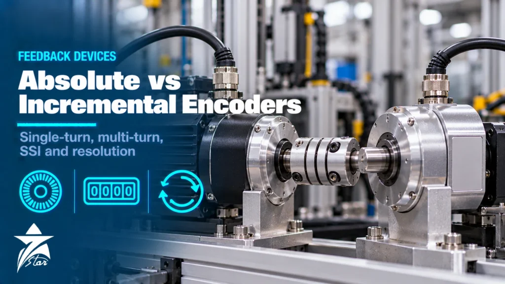
A rotary encoder looks like a simple component until one fails and the replacement does not talk to the drive, loses position after a power cut or miscounts at full speed. The first choice in every specification is absolute vs incremental encoder, and it is followed by a string of decisions that matter just as much: single-turn or multi-turn, the electrical interface (HTL, TTL, SSI, BiSS C, EnDat or a fieldbus), resolution, mechanical mounting and cabling. This guide explains how each type works, compares the interfaces, shows how to size resolution and output frequency, and lists the data to collect before you order or replace an encoder.
How an Incremental Encoder Works
An incremental encoder produces a train of pulses as its shaft rotates. An optical version shines light through a disc with a fine pattern of lines; a magnetic version reads a magnetised ring with a Hall-effect or magnetoresistive sensor. Two channels, A and B, are offset by 90 electrical degrees (quadrature). The controller counts pulses for distance and uses which channel leads to determine direction. A third channel, Z (index or marker), gives one pulse per revolution and is used for homing.
Because quadrature has four edges per cycle, the receiving counter can evaluate 1x, 2x or 4x. A 1,024 pulses-per-revolution (PPR) encoder read with 4x decoding gives 4,096 counts per revolution. Datasheets usually quote PPR or lines per revolution, so confirm which multiplication the counter or drive applies before comparing numbers.
The limitation is fundamental: an incremental encoder only reports change. When power is removed or a pulse is missed, the controller no longer knows the true position until the axis is homed again.
Incremental output types
- TTL / RS-422 line driver: 5 V differential signals (A, /A, B, /B, Z, /Z). Good noise rejection and high frequency; the common input for servo drives and high-speed counter cards.
- HTL push-pull: switches at the supply voltage, typically 10–30 V DC. Larger signal swing and good noise margin on long cables; suits 24 V PLC inputs and many VFD encoder cards.
- Open collector (NPN/PNP): simple and cheap, but limited frequency and more sensitive to noise; best kept to short runs and low speeds.
- Sin/cos 1 Vpp: analogue sine and cosine signals that the drive interpolates to very high resolution; used in precision servo and machine tool feedback.
How an Absolute Encoder Works
An absolute encoder assigns a unique digital word to every shaft position. Optical designs use a disc with several concentric code tracks (often Gray code, where only one bit changes between neighbouring positions); magnetic designs read a diametrically magnetised element with a multi-axis sensor. When power is applied, the encoder simply reports where the shaft is. No homing run is required, which is why absolute encoders dominate cranes, hoists, gates, stacker-reclaimers, rotary indexers and any axis where an unexpected move after a power cut is unsafe or expensive.
Resolution is expressed in bits. A 12-bit single-turn encoder resolves 4,096 positions per revolution, 13 bits gives 8,192 and 16 bits gives 65,536. Servo motor feedback commonly goes higher still.
Single-turn vs multi-turn
A single-turn absolute encoder repeats its code every revolution. That is fine for a rotary table or a directly driven valve stem, but a hoist drum or lead screw turns many times across its travel. A multi-turn encoder adds a revolution counter, for example 12 bits (4,096 revolutions) on top of the single-turn resolution. Three methods are used to keep the revolution count without mains power:
- Mechanical gear train: a set of geared code discs counts turns. No battery, robust, but adds size and moving parts.
- Energy-harvesting (Wiegand wire): a magnetic pulse generated on each revolution powers the counting electronics, so turns are recorded even when the shaft moves with the power off.
- Battery-buffered: common in servo motor feedback. Compact, but the battery is a maintenance item; when it is flat the position is lost and the axis must be re-referenced.
Absolute vs Incremental Encoder Comparison
| Criterion | Incremental | Absolute single-turn | Absolute multi-turn |
|---|---|---|---|
| — | — | — | — |
| Position after power loss | Lost; homing required | Known within one revolution | Known over full travel |
| Typical outputs | TTL/RS-422, HTL, open collector, sin/cos | SSI, BiSS C, EnDat, fieldbus, analogue | SSI, BiSS C, EnDat, fieldbus |
| Wiring | 6–8 signal cores plus power | Clock and data pairs plus power, or a network cable | Same as single-turn |
| Speed feedback for drives | Excellent, direct | Possible; often combined with incremental tracks | Possible; often combined with incremental tracks |
| Relative cost | Lowest | Medium | Highest |
| Typical uses | Conveyors, motor speed loops, length measurement | Rotary tables, valves, steering angle | Cranes, hoists, winches, lead screws, telescopic axes |
Many absolute encoders also provide incremental sin/cos or TTL tracks so that a drive can close a fast speed loop while reading the absolute position at power-up.
Serial Interfaces: SSI, BiSS C, EnDat and Others
Absolute position has to reach the controller as a digital word, and the interface determines speed, diagnostics and compatibility. This is where most replacement mistakes happen, because two encoders with identical housings can speak entirely different protocols.
- SSI (Synchronous Serial Interface): the controller sends a clock burst and the encoder shifts out its position word on a differential data line. It is simple, widely supported and one-way only. Typical clock rates range from roughly 100 kHz to 2 MHz, and the usable rate falls as cable length increases. You must match word length (for example 13, 24 or 25 bits), code (Gray or binary) and data format (left- or right-justified) to the receiving card.
- BiSS C: an open protocol on similar hardware to SSI but bidirectional, with CRC error checking, line-delay compensation and clock rates up to 10 MHz. Register access allows parameters and diagnostics to be read.
- EnDat 2.2: a proprietary bidirectional interface from Heidenhain. With propagation-delay compensation it supports clock rates up to 16 MHz on supporting models, and it transmits additional data such as temperature, warnings and an electronic identification label.
- Hiperface and single-cable variants: used mainly on servo motors, combining sin/cos tracks with a parameter channel; single-cable versions run the encoder signal inside the motor power cable.
- Fieldbus and Ethernet encoders: PROFINET, EtherNet/IP, EtherCAT, PROFIBUS, CANopen and IO-Link versions put the encoder directly on the network. Wiring is simpler and diagnostics are richer, but cycle time and network configuration must suit the control loop; see our comparison of industrial communication protocols.
Sizing Resolution and Output Frequency
Resolution should come from the application, not from the largest number in the catalogue. Work it through in three steps:
- Define the required position resolution at the load. For example, a hoist must be positioned to 1 mm and the drum moves 500 mm of rope per revolution.
- Convert to counts per revolution at the encoder shaft. 500 mm / 1 mm = 500 positions; apply a margin of at least four to five times so control and filtering are not starved of counts, giving roughly 2,500 positions, which a 12-bit (4,096) single-turn resolution covers.
- Check travel for multi-turn. If the drum makes 60 revolutions over the full travel, a 12-bit multi-turn counter (4,096 turns) is more than adequate.
For incremental encoders, the output frequency often limits the choice:
Output frequency (Hz) = PPR × rpm / 60. A 2,048 PPR encoder at 3,000 rpm produces about 102 kHz per channel. Compare this with the encoder’s rated maximum frequency and, just as important, with the maximum input frequency of the PLC high-speed counter or drive feedback card. A standard 24 V digital input will not count 100 kHz; you need a dedicated counter module. Our PLC and I/O card range includes high-speed counter and SSI input modules for this purpose.
Remember that resolution, accuracy and repeatability are different. A 16-bit encoder with poor coupling alignment can report a fine-grained but wrong position. Accuracy is set by the disc or magnet, the bearing system and the installation as much as by the bit count.
Mechanical Selection and Mounting
The mechanical interface determines whether the encoder survives. Collect these points:
- Shaft type: solid shaft (connected through a flexible coupling) or hollow / blind hollow shaft (slid over the machine shaft and held by a torque arm or stator coupling).
- Shaft diameter and flange: clamping flange or synchro flange, and the common 58 mm housing size used across many manufacturers; compact 36–40 mm and large hollow-shaft heavy-duty versions also exist.
- Shaft loads: permitted radial and axial loads. Never drive a solid-shaft encoder directly from a belt or gear without a supporting bearing.
- Ingress protection: IP65 for dry indoor areas, IP66/IP67 for washdown, outdoor and dusty sites. Shaft-seal versions trade a little speed for protection.
- Shock and vibration: heavy-duty encoders for steel mills, cranes and mobile machines have larger bearings and reinforced housings.
- Hazardous areas: encoders for Zone 1 or Zone 2 must carry the correct Ex marking; check gas group and temperature class against the area classification.
Use a coupling rated for the misalignment you actually have. A rigid connection between a motor shaft and an encoder shaft transfers runout directly into the encoder bearings and shortens their life significantly. For hollow-shaft units, the torque arm must allow the encoder to float axially and radially while stopping rotation.
Wiring and Noise Immunity
Most encoder faults reported as “intermittent counting” are wiring and grounding problems:
- Use a twisted-pair, overall-shielded cable with pairs matched to A/A-bar, B/B-bar, Z/Z-bar, clock and data.
- Terminate the shield 360° at both ends where the equipotential bonding is good, or follow the drive manufacturer’s specific instruction.
- Route encoder cables away from motor power cables, especially VFD outputs, and cross them at right angles.
- Check voltage drop on long runs; a 5 V encoder at the end of a long cable may see too little supply voltage.
- Use line-driver (differential) signals for anything beyond short distances. Single-ended signals pick up noise easily.
When an encoder feeds a vector-controlled drive or servo, follow the drive’s encoder module documentation for supply, termination and signal level. Our servo drive and AC drive categories list feedback options for typical platforms.
Absolute vs Incremental Encoder: Common Mistakes
- Replacing an SSI encoder with one of different word length, Gray/binary code or clock settings, so the position jumps or reads garbage.
- Choosing single-turn for an axis that turns several times, then discovering the position wraps after one revolution.
- Wiring a TTL line-driver encoder to 24 V inputs that cannot read 5 V differential signals.
- Exceeding the counter input frequency at maximum motor speed.
- Mounting a solid-shaft encoder with a rigid coupling or driving it from a belt.
Troubleshooting Encoder Problems
- Position drifts slowly: look for coupling slip, a loose set screw, or noise causing occasional extra counts. Check the Z pulse position over several revolutions; if it moves relative to the mechanical reference, the coupling is slipping.
- Random jumps or count errors: inspect shield termination, cable route and connectors. Measure the differential signals with an oscilloscope; clean square waves with consistent amplitude indicate a healthy encoder.
- Drive trips on feedback fault: confirm supply voltage at the encoder end, then signal levels. For serial encoders, check the CRC or alarm bits reported by the drive.
- Absolute position wrong after replacement: the new encoder needs a zero offset or preset; many SSI and fieldbus encoders have a preset input or parameter.
Operating in GCC Conditions
Encoders on outdoor conveyors, port cranes, water intakes and oilfield equipment in Oman and the wider GCC see high ambient temperatures, direct sun, fine dust and, near the coast, salt-laden humidity. Check the maximum operating temperature on the datasheet rather than assuming the housing will cope; sun-exposed metal surfaces can run far above shade air temperature, so a sunshade or cover helps. Specify at least IP66 with shaft seals for dusty and coastal locations, stainless or coated housings near seawater, and connectors with proper sealing or a fixed cable gland. Magnetic encoders tolerate dust and condensation better than open optical designs, while optical encoders generally offer higher accuracy for precision axes.
Encoder Selection Checklist
- Absolute or incremental, and single-turn or multi-turn (number of revolutions over full travel)
- Required resolution at the load and resulting PPR or bits
- Output or interface: HTL, TTL/RS-422, sin/cos, SSI, BiSS C, EnDat, fieldbus or analogue
- For SSI: word length, Gray or binary, clock rate, data format
- Supply voltage and maximum cable length
- Maximum speed and resulting output frequency versus receiver input limit
- Shaft type and diameter, flange, coupling or torque arm
- Ingress protection, temperature range, shock and vibration ratings
- Hazardous area marking if applicable
- Connector type and pinout, or cable length
- Receiving device: drive model, PLC counter or SSI card
Encoders We Supply
These examples cover incremental and absolute encoders with different interfaces.
| Product | Type | Where it fits |
|---|---|---|
| Autonics E40S6-2500-6-L-5 Rotary Encoder Incremental | Incremental encoder | Speed and position feedback on general machinery. |
| SICK DFS60B-S4PA10000 Incremental Encoder, 10,000 PPR | Incremental encoder, 10,000 PPR | High-resolution speed and position. |
| Kübler Sendix 5000 Incremental Encoder Shaft Version 5000 PPR | Incremental encoder | Shaft-mounted speed feedback. |
| SICK AFS60A-S4AM065536 SSI Singleturn Encoder, 16 Bit | Singleturn absolute encoder, SSI | Position within one turn that is kept through power loss. |
| Kübler Sendix 5863 Multiturn Absolute Encoder SSI BiSS | Multiturn absolute encoder | Position over many turns without a homing run. |
| SICK AFM60A-S4NB018x12 PROFINET Absolute Encoder | Absolute encoder, PROFINET | Networked position feedback directly to the PLC. |
Send the shaft or hollow shaft size, resolution, interface, supply voltage and connector type through our quote request form.
Sourcing Rotary Encoders Through Seven Star LLC
Seven Star LLC supplies incremental and absolute rotary encoders on request for plants in Oman and across the GCC, from standard 58 mm industrial units to heavy-duty hollow-shaft and fieldbus encoders from manufacturers such as Heidenhain, SICK, Kübler and Baumer. We help with selection and cross-checking part numbers against your existing model codes, and availability and lead time are confirmed at quotation.
Replacing or specifying an encoder? Send us the label photo, model code, interface type and the drive or PLC it connects to, and we will return a matched quotation.
Frequently asked questions
What is the main difference between an absolute and an incremental encoder?
An incremental encoder outputs pulses as the shaft turns, so the controller only knows position by counting from a reference point and loses it when power is removed. An absolute encoder outputs a unique code for every shaft position, so the true position is available immediately at power-up without a homing run.
Do I need a single-turn or a multi-turn absolute encoder?
Use single-turn when the measured motion stays within one revolution of the encoder shaft, such as a rotary table or a valve stem driven directly. Use multi-turn when the shaft makes many revolutions over the travel, such as a crane hoist drum, a winch or a lead screw, so the encoder must also count revolutions and keep that count through power loss.
What is the difference between SSI, BiSS C and EnDat?
SSI is a simple one-way synchronous serial interface in which the controller clocks out the position word, typically at clock rates up to about 2 MHz. BiSS C is an open, bidirectional protocol with CRC checking and clock rates up to 10 MHz. EnDat 2.2 is a proprietary bidirectional interface from Heidenhain that supports clock rates up to 16 MHz with propagation delay compensation and can transfer additional data such as diagnostics.
How do I calculate the output frequency of an incremental encoder?
Multiply the pulses per revolution by the shaft speed in revolutions per second. For example, a 2,048 PPR encoder at 3,000 rpm (50 rev/s) produces about 102 kHz per channel. Check that this is below both the encoder's rated output frequency and the maximum input frequency of the counter card or drive feedback module.
Should I choose TTL (RS-422) or HTL outputs?
TTL/RS-422 line driver outputs use 5 V differential signals and suit high frequencies and most servo and drive feedback inputs. HTL push-pull outputs switch at the supply voltage, typically 10–30 V DC, and give better noise margin on long cable runs and on PLC inputs designed for 24 V signals. Match the output type to what the receiving input accepts before ordering.
What information is needed to replace an encoder?
Send the full model code from the label, shaft type and diameter, flange type, output or interface type, supply voltage, resolution (PPR or bits), connector or cable details and the receiving device. A photo of the label and the mounting arrangement helps confirm an exact match or a suitable cross-reference.
Was this guide helpful?One click helps us write better guides for engineers.
Thank you! Glad it helped. Need this equipment for your project? Request a quotation
Thank you. We will use this to improve the guide.