Low-range differential pressure for air, gas and clean liquids
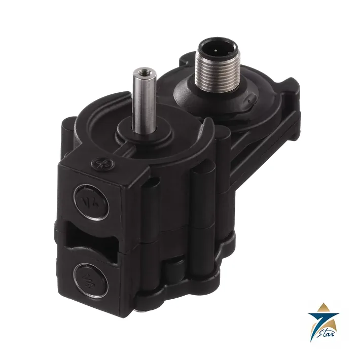
The JUMO MIDAS DP10 (type 401050) is a compact differential pressure transmitter with a piezo-resistive silicon sensor in a PBT housing, measuring the difference between two pressures in liquid and gaseous media and converting it to an analog signal. Nine ranges from 0 to 0.4 bar up to 0 to 16 bar are offered, which suits filter monitoring, flow measurement across orifices and level measurement in closed vessels.
Both ports are on the same body and can take a 6 mm stainless steel tube, a 6 mm screwed pipe joint in stainless steel or brass, or two G 1/8 threads to EN 837. The data sheet notes that for water above 50 C a pipe or hose of at least 200 mm (for 85 C water) must separate the transmitter from the medium.
Technical specifications
| Parameter |
Specification |
| Data sheet type |
401050/000 |
| Measuring ranges |
0 to 0.4, 0.6, 1.0, 1.6, 2.5, 4, 6, 10, 16 bar differential pressure |
| Max. system pressure |
5 bar (0.4 bar range) up to 30 bar; 25 bar for 6 bar range |
| Bursting pressure |
60 bar (all listed ranges) |
| Overall error |
Between 1.5 % and 2.5 % of full scale depending on range (per data sheet table) |
| Long-term stability |
0.4 % to 0.6 % per annum depending on range |
| Output |
4 to 20 mA two-wire; 0.5 to 4.5 V ratiometric; 0 to 10 V three-wire |
| Compensated temperature |
-15 to +85 C; maximum ambient temperature 60 C |
| Parts wetted |
Stainless steel 1.4571, 1.4435 or 1.4305; PBT GF30 or PA66; FPM seal |
| Process connection |
6 mm stainless tube; 6 mm screwed joint (steel or brass); 2 x G 1/8 EN 837 |
| Electrical connection |
Fixed cable 2 m, M12 x 1 round connector, bayonet connector DIN 72585 |
| Housing material |
PBT |
Ordering the DP10
The order code is 401050/000-input-output-process connection-68 housing-601 seal-electrical connection. Input codes run from 452 (0 to 0.4 bar) through 453, 454, 455, 456, 457, 458 and 459 to 460 (0 to 16 bar), with 999 for special ranges. Output codes are 405 (4 to 20 mA), 412 (0.5 to 4.5 V) and 415 (0 to 10 V). Process connection codes are 297, 305, 306 and 593, and electrical connections are 11 (cable), 36 (M12) and 53 (bayonet).
The data sheet lists accessories with part numbers: a 4-pole straight M12 connector with 2 m PVC cable (00404585), an angled one (00409334), angled and straight mounting brackets (00448193, 00490132) and a bayonet jack with 3 m cable (00463392).
Installation points that affect accuracy
Zero offset is within 0.3 percent and thermal hysteresis is stated as plus or minus 1 percent for ranges at or below 0.6 bar and plus or minus 0.5 percent above that. For simultaneous pressure on both ports, the system pressure limit applies, so check the line pressure and not only the differential. The customer must also test that the wetted materials are compatible with the measured medium.
Orient and mount the unit so tube runs are short; fit the mounting bracket for vibration-prone sites, and use the connector with the cable length that suits the panel.
Selection checks for the MIDAS DP10
Start with the differential pressure the application actually produces, not the static line pressure. For filter monitoring, find the pressure drop across a clean filter and the drop at which the filter should be changed, then choose the smallest range that still covers the higher value with some margin. For flow measurement across an orifice, take the expected maximum differential from the orifice calculation. For level in a closed vessel, work out the differential from the liquid height and density at the highest level. Choosing a range far larger than needed reduces resolution, while a range that is too small risks overload during upsets.
Next, confirm the static pressure on both ports against the system pressure limit for the chosen range, and check that the medium is compatible with the wetted stainless steel, plastic and FPM seal materials listed above. Finally, decide which output signal the receiving PLC, controller or display accepts, and which electrical connection suits the panel or field junction box.
Installation and impulse lines
Keep the high- and low-pressure tubing as short and as similar in length as practical, and slope it so that gas bubbles can escape in liquid service and condensate can drain in gas service. Mark the high and low sides clearly during installation, because swapped connections are a frequent cause of a reading that moves the wrong way. Where the transmitter is mounted on a duct, frame or pump skid, use a bracket and route the tubes so that vibration is not passed straight into the body.
Commissioning the transmitter
With both ports open to the same pressure, check that the output reads zero within the tolerance stated on this page. Then apply a known differential, either from the process or from a calibrator, and confirm that the controller scaling matches the selected range. Record the as-found and as-left values so that later checks can be compared with the starting point.
Heat, dust and humidity in Oman and the GCC
The maximum ambient temperature given in the specification is an important limit in the Gulf. Air-handling units on rooftops, pump houses without cooling and outdoor skids can exceed it in summer, so choose a shaded, ventilated mounting point or place the transmitter inside a cooled panel with the tubing run to the process. Dust and sand can block small ports and fittings during installation, so keep protective caps on until the tubes are connected. In humid coastal areas, make sure that cable entries and connectors are sealed so moisture does not reach the electrical connection.
Periodic checks
Check the zero during planned maintenance, inspect the tubing for kinks or leaks, and compare the reading with a second instrument where one is available. Given the long-term stability figures quoted above, an annual verification is a sensible starting point for most utility applications.
Documents and quotation
Please check the differential range, line pressure and connection type before ordering, because the final code depends on the installation. The attached manufacturer file, JUMO MIDAS DP10 data sheet 401050 (EN, V1.00, 2021-11-04), carries the authoritative data. Send the code you selected and the quantity, and we respond with a written offer. Similar instruments: Pressure Instrumentation.


















Reviews
There are no reviews yet.