A 15 kW FC 302 in frame B3 with dual high- and normal-overload ratings
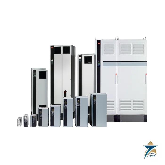
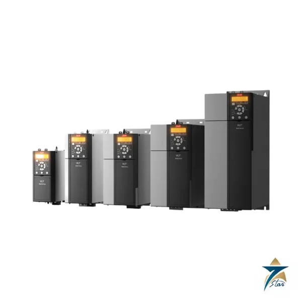
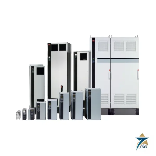
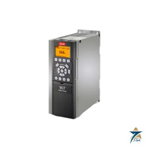
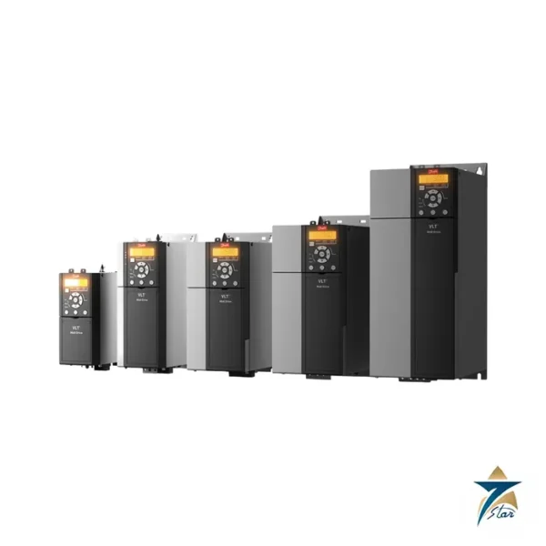
The 131F8140 is Danfoss order number for the FC-302P15KT5E20H2XGCXXXSXXXXAXBXCXXXXDX, a VLT AutomationDrive FC 302 that is rated 15 kW (20 hp) at high overload and 18.5 kW (25 hp) at normal overload. That dual rating is the main selection point at this size: a constant-torque conveyor, extruder or hoist should be sized on the 15 kW high-overload figure, whereas a variable-torque centrifugal pump or fan may use the 18.5 kW normal-overload rating. The drive is housed in the IP20 B3 frame, carries the RFI filter and a graphical panel, and has coated electronics.
Technical specifications
| Parameter |
High overload (HO) / normal overload (NO) |
| Order number / type code |
131F8140 / FC-302P15KT5E20H2XGCXXXSXXXXAXBXCXXXXDX |
| Shaft output |
15 kW (20 hp) HO / 18.5 kW (25 hp) NO |
| Output current 380-440 V |
32 A continuous, 51.2 A intermittent (HO) / 37.5 A, 41.3 A (NO) |
| Output current 441-500 V |
27 A, 43.2 A (HO) / 34 A, 37.4 A (NO) |
| Apparent power 400 V |
22.2 kVA |
| Maximum input current 380-440 V |
29 A continuous (HO) / 34 A (NO) |
| Power loss |
379 W (HO) / 465 W (NO); efficiency about 98% |
| Enclosure, frame |
IP20 chassis, B3 |
| Dimensions H x W x D |
399 x 165 x 249 mm (262 mm deep with A/B option); 225 mm wide with two C options |
| Maximum cable cross-section |
10 mm2 (AWG 7) for mains, motor, brake and load sharing |
| Recommended fuse |
gG-40 (maximum gG-63); Moeller PKZM4-50 breaker, 50 A trip |
| Danfoss store data |
Net weight 10.39 kg, gross weight 11.41 kg, volume 57.585 l, EAN 5702427481381, ECCN US 3A999.a |
Type code of 131F8140
| Type-code part |
Meaning |
| P15K |
15 kW HO / 18.5 kW NO |
| T5 |
380-500 V three phase |
| E20 |
IP20 chassis |
| H2 |
RFI filter |
| X |
No brake chopper |
| G |
Graphical local control panel |
| C |
Coated PCB |
| AX BX CX DX |
No A, B, C0/C1 or D options |
Installation and selection at 15 kW
B-frame drives need 200 mm of free air above and below, twice the 100 mm of the A frames, so panel layout matters. At 32 A output the drive needs a feeder and fuse of at least the 29 A input current, and the recommended gG-40 fuse reflects that. This code has no brake chopper: decelerating loads need an external brake solution. The operating guide lists the usual protections, including thermal motor protection, and motor cable lengths of up to 150 m screened for the FC 302.
When replacing an older drive, compare nameplate current rather than kW alone and confirm which overload class your duty needs. The Danfoss store page also shows an “Upgrade available” notice for this code, so confirm with us whether the current revision or a successor is being supplied.
The output stage described in the Danfoss FC 300 guide delivers 0 to 100 percent of the supply voltage at an output frequency of 0 to 590 Hz, with flux control working from 0 to 300 Hz. Ramp times can be set from 0.01 to 3600 seconds, and the output may be switched without limit, which suits applications with frequent output contactor operation.
Panel layout and wiring for the B3 frame
The 131F8140 is an IP20 chassis drive, so it must be installed inside a cabinet or a closed electrical room. When the cabinet is laid out, reserve the free air space above and below the drive, keep heat-sensitive components out of its exhaust path, and size the cabinet cooling for the power loss listed in the table at the duty class you have chosen. The normal-overload loss figure is the higher of the two, so use it if the drive will run a pump or fan at the normal-overload rating.
Use screened motor cable and terminate the screen with the cable clamps provided, so that the built-in RFI filter can do its job. Keep mains, motor and control wiring physically separated, and keep cable cross-sections within the terminal limits given above. Where the drive has to stop high-inertia loads quickly, remember that this code has no brake chopper and plan an external solution at the design stage, not after the first overvoltage trip.
Commissioning with the graphical panel
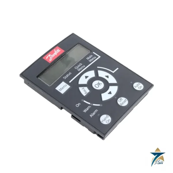
The graphical local control panel makes start-up straightforward. Enter the motor nameplate data, select the overload class that matches the application, and run automatic motor adaptation where the motor can be safely uncoupled or left stationary as the operating guide describes. Set ramp times to suit the machine, configure the speed reference and start commands, and test the stop and emergency functions before the machine is handed over. Save the final parameter set in the panel and in a project file so that a replacement drive can be configured without repeating the full commissioning.
Maintenance practice
Coated electronics give extra resistance to contaminated air, but a drive still needs clean cooling. At planned intervals, isolate the supply, wait for the DC link to discharge as stated in the operating guide, and inspect the heatsink, fans and terminals. Check the alarm and fault log before resetting the drive, and note repeated warnings such as high temperature, which often point to blocked air paths or a failed cabinet fan rather than a drive fault.
Site conditions in Oman
Motor control rooms in Oman can become very hot in summer when air conditioning fails or is undersized, and fine dust enters through doors and cable openings. Check the expected cabinet temperature against the Danfoss derating information, seal unused cable entries, and keep filters on cabinet fans clean. Where the drive serves pumps at remote sites, a simple temperature alarm inside the panel helps operators react before the drive trips on heat. Recording the cabinet temperature during the hottest weeks of the first summer also shows whether the cooling design has enough margin for the years ahead.
Documents and quotation
The Danfoss operating guide for enclosure sizes A-C is attached as a download. Related: the Danfoss VLT AutomationDrive FC 302 page and the AC drives category. Please send us the duty data and label of the unit you replace, and confirm the code with us before ordering.





Reviews
There are no reviews yet.