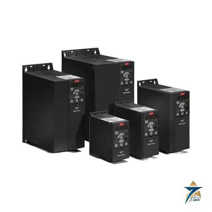
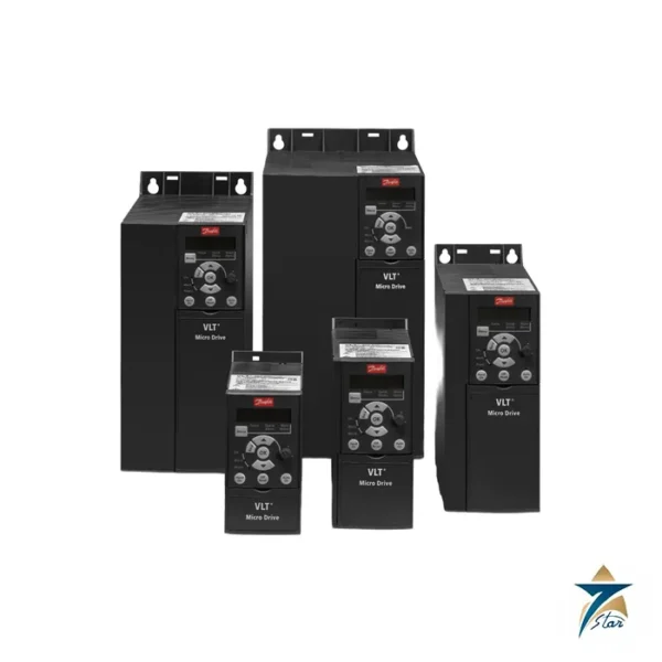
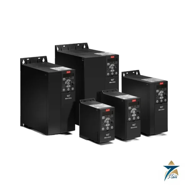
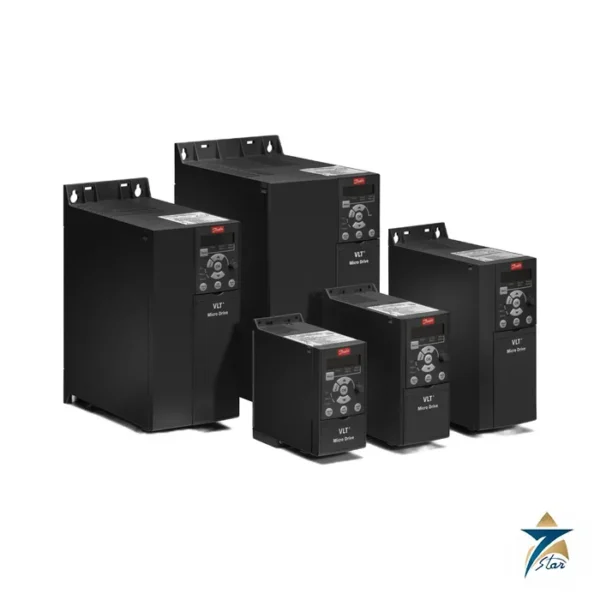
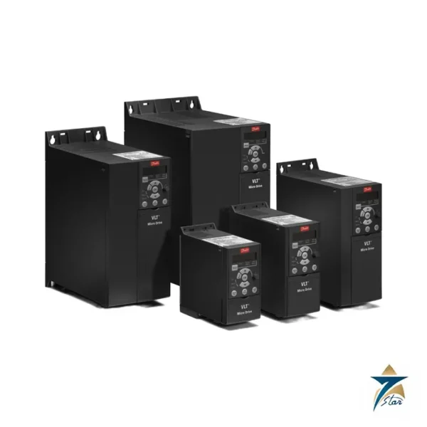
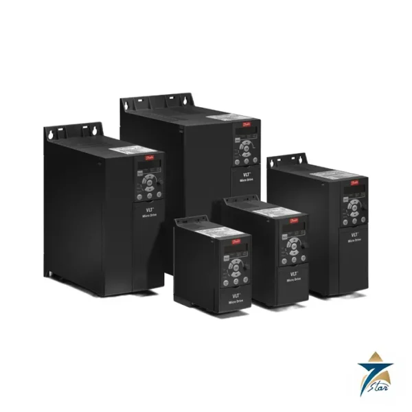
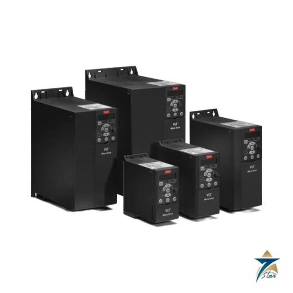
The 4 kW VLT Micro Drive for 400 V motors, supplied without RFI filter
The 136N8931 is Danfoss order number for FC-051P4K0T4E20HXBXCXXXSXXX, the 4.0 kW (5 hp) three-phase 380-480 V VLT Micro Drive FC 51 in frame M3. It combines the highest rating of the small M3 frame with an integrated brake chopper and no RFI filter. Typical loads are 4 kW pumps, blowers and conveyor drives in plants that handle filtering at panel level, and as a like-for-like replacement for an existing unfiltered unit. Its output of 9.0 A at 380-440 V is 25% above the 3.0 kW drive (132F0024) in the same enclosure.
Technical specifications
| Parameter |
Specification |
| Order number / type code |
136N8931 / FC-051P4K0T4E20HXBXCXXXSXXX |
| Typical shaft output |
4.0 kW (the design guide table lists 5.5 hp) |
| Supply |
3 x 380-480 V AC, +/-10%, 50/60 Hz |
| Output at 380-440 V |
9.0 A continuous, 13.7 A intermittent |
| Output at 440-480 V |
8.2 A continuous, 12.3 A intermittent |
| Line current at 380-440 V |
14.4 A continuous, 20.2 A intermittent |
| Line current at 440-480 V |
12.4 A continuous, 17.5 A intermittent |
| RFI filter |
None (type code HX) |
| Frame, degree of protection |
M3, IP20 chassis |
| Overall size (H x W x D) |
239 x 90 x 194 mm; 294 mm high with decoupling plate |
| Weight |
3.0 kg |
| Losses, best case / typical |
98.5 W / 133.5 W |
| Efficiency at rated current, best / typical |
98.0% / 97.3% |
| Danfoss store data |
Net weight 3 kg, gross weight 3.3 kg, EAN 5710108968335, ECCN US 3A999.a |
Ordering code explained
| Segment |
Decoded as |
| P4K0 |
4.0 kW |
| T4 |
Three phase 380-480 V AC |
| E20 |
IP20 / chassis |
| HX |
No RFI filter |
| B |
Brake chopper |
| X |
No local control panel |
| C |
Coated PCB |
| SXXX |
Latest standard software |
Application and installation guidance
At 14.4 A input current the feeder and fuse are sized well above the 3 kW unit, and the M3 frame needs the full 100 mm clearance above and below when mounted side by side. The decoupling plate kit 132B0107 and the IP21 kit 132B0110 listed for M3 drives apply here. Because there is no internal filter, plan the EMC measures of the machine: screened motor cable, short runs and an external filter where limits require it. The control supply on terminal 12 delivers 50 mA on M3, so supply heavy sensor loads externally. Output frequency runs from 0 to 200 Hz in VVC+ mode and from 0 to 400 Hz in U/f mode, with ramp times from 0.05 to 3600 s, and heat-sink temperature monitoring plus earth-fault protection on the motor terminals are standard.
The two operating documents attached to this page include the PELV isolation of control circuits and the electronic motor protection. Danfoss flags this order number as nearing the end of its life (last buy June 30, 2026; last delivery September 30, 2026), so treat availability as unconfirmed until we reply.
For wiring, the Danfoss FC 51 guide lists a maximum cable cross-section of 4 mm2 for mains and motor terminals and 1.5 mm2 for control wires. Relative humidity may be 5 to 95 percent without condensation, and the guide describes derating when the drive is installed above 1000 m, with a limit of 3000 m. Check these values against the installation conditions on site.
Selecting the 136N8931 for a 4 kW motor
Start from the motor nameplate rather than the kilowatt figure alone. A 4 kW motor that draws more than the continuous output current listed above, for example an older or low-efficiency design, may need the next size up. Also check whether the load needs the intermittent current for starting: loaded conveyors and positive displacement pumps lean on it much more than centrifugal fans. Where the supply sits at the upper end of the voltage range, use the 440-480 V current values, which are lower.
- Confirm that an unfiltered drive is acceptable for the installation; residential or mixed-use supplies normally call for a filtered version or an external filter.
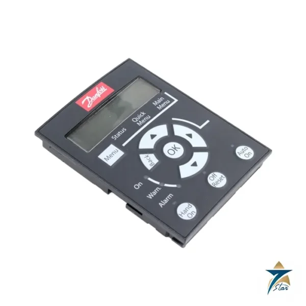
- Decide whether a local control panel is needed, since this type code has none; commissioning without one requires a separate keypad or PC software.
- If the drive replaces an existing unit, match the full type code, not just the power rating, so the brake chopper and coating are carried over.
Installation and commissioning
Mount the drive vertically on a flat back plate with the clearances noted above, and use the decoupling plate to clamp the screen of the motor cable. Earth the drive and motor with conductors sized for the fault current, then connect mains and motor within the terminal cross-section limits. If a braking resistor is fitted to the brake chopper, route its cable away from control wiring because it carries pulsed DC.
At first start, enter the motor data and run an automatic motor adaptation if the application uses VVC+ control. Set the ramps to suit the mechanics, check rotation direction with the motor uncoupled, then couple and observe current under real load.
Maintenance and fault finding
The FC 51 has no user-replaceable parts beyond its fan path, so maintenance is mainly about cleanliness and connections. Blow out dust from the heat sink during planned shutdowns, retighten mains and motor terminals, and check that the cable screen clamp is still making good contact. When a trip occurs, note the alarm before resetting: earth faults point to cable or motor insulation, overvoltage during stopping points to short ramps or a missing braking resistor, and heat-sink temperature alarms point to blocked airflow or a hot cabinet.
Application notes for Oman and GCC conditions
This IP20 chassis drive needs a cabinet. In Omani summers, panels mounted outdoors or in plant rooms without air conditioning can exceed the ambient the drive is designed for, so add cabinet cooling or a sunshade, and do not stack heat sources above the drive. Fine sand blocks heat-sink fins quickly; filtered fans with regularly changed mats help. The coated PCB in this type code gives some protection against humidity and corrosive air, which is useful on coastal and desalination sites, but it does not replace a sealed enclosure and anti-condensation heating where overnight condensation is likely. Given the end-of-life status noted above, plant owners standardising on this model may also want to review a successor drive for future spares.
Documents and quotation
The design guide and the unfiltered-version operating guide are attached as downloads. Related pages: the Danfoss VLT Micro Drive FC 51 family page and the AC drives category. Please send the label of the unit you want to match and confirm the code with us before ordering.





Reviews
There are no reviews yet.