Machinery vibration straight to a 4-20 mA loop
The PCB Piezotronics 642A01 is an industrial vibration sensor with a 4-20 mA output proportional to velocity, covering 0 to 1 in/sec peak (0 to 25.4 mm/s peak) from 3 to 1,000 Hz. A signal in current form can run long cable distances to a PLC, DCS or machinery protection input without a separate signal conditioner.
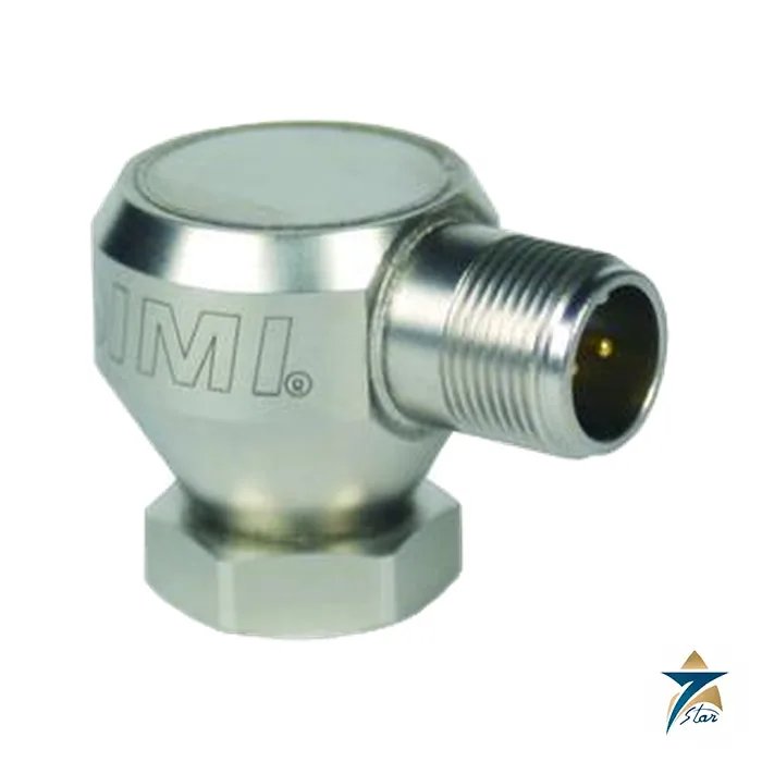
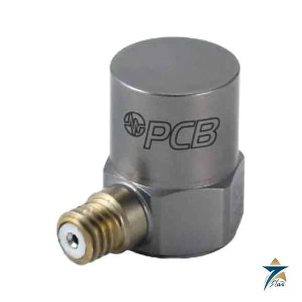
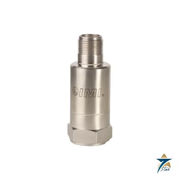
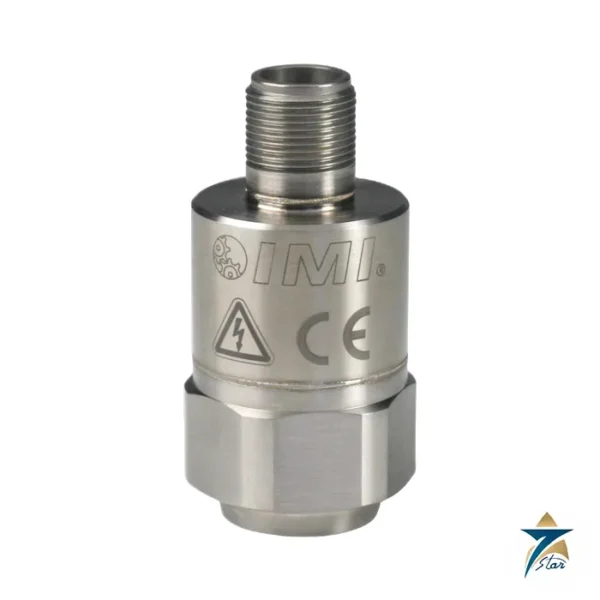
The sensor has a ceramic shear sensing element in a welded hermetic stainless steel housing, IP68 enclosure rating and a side-exit 2-pin MIL-C-5015 connector. It is powered from 12 to 30 VDC in a standard two-wire loop.
Technical specifications
| Parameter |
Specification |
| Measurement range |
0.0 to 1.0 in/sec pk (0.0 to 25.4 mm/s pk) |
| Output |
4-20 mA |
| Frequency range (+/-10 %) |
3 to 1,000 Hz (180 to 60,000 cpm); current fluctuates below 5 Hz |
| Broadband resolution |
0.005 in/sec pk (0.13 mm/s pk) typical |
| Non-linearity |
+/-1 % |
| Temperature range |
-40 to 185 F (-40 to 85 C) |
| Enclosure rating |
IP68 |
| Excitation voltage |
12 to 30 VDC |
| Settling time (within 2 %) |
Under 15 s |
| Electrical isolation (case) |
Above 10^8 ohm |
| Sensing element / geometry |
Ceramic / shear |
| Housing / sealing |
Stainless steel / welded hermetic |
| Size (hex x height) |
7/8 in x 1.41 in (22.2 mm x 35.8 mm) |
| Weight |
3.8 oz (108 g) |
| Mounting thread |
1/4-28 UNF; stud torque 3 to 4 ft-lb (4.1 to 5.4 Nm); hex nut 2 to 3 ft-lb (2.7 to 4.1 Nm) |
| Connector / position |
2-pin MIL-C-5015 / side; pin A 4-20 mA positive, pin B negative |
| Supplied accessories |
Model 080A162 mounting stud; ICS-4 single-axis calibration from 0 Hz to the upper 10 % frequency |
Options, installation and loop behaviour
The spec sheet lists EX (hazardous area approval, contact the factory), M (metric mount with accessory M080A163A) and RV (buffered analog signal output of 100 mV/g +/-20 percent, on a 3-pin MIL-C-5015 connector). The RV option is useful when the same sensor should feed a portable analyser as well as a loop.
Use a smooth, flat, drilled and tapped surface and silicone grease on the interface. A 1/8 in hex key (3 mm for metric) is needed for the stud, and the stud torque must be higher than the nut torque so the sensor can be removed again. The sensor is calibrated before shipment to the amplitude response shown in ICS-4.
Two details from the spec sheet matter for loop design. The output current fluctuates at frequencies below 5 Hz, and the settling time to within 2 percent of the value is under 15 seconds, so alarm logic should allow for a start-up delay. The 2-pin MIL-C-5015 connector carries the 4-20 mA positive on pin A and negative on pin B, and the case is electrically isolated at more than 10^8 ohm.
What to confirm before ordering
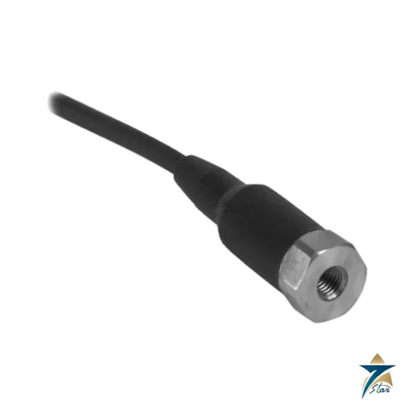
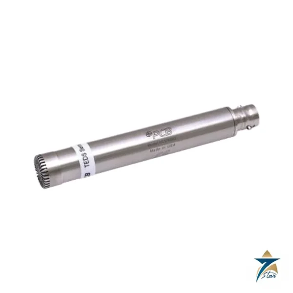
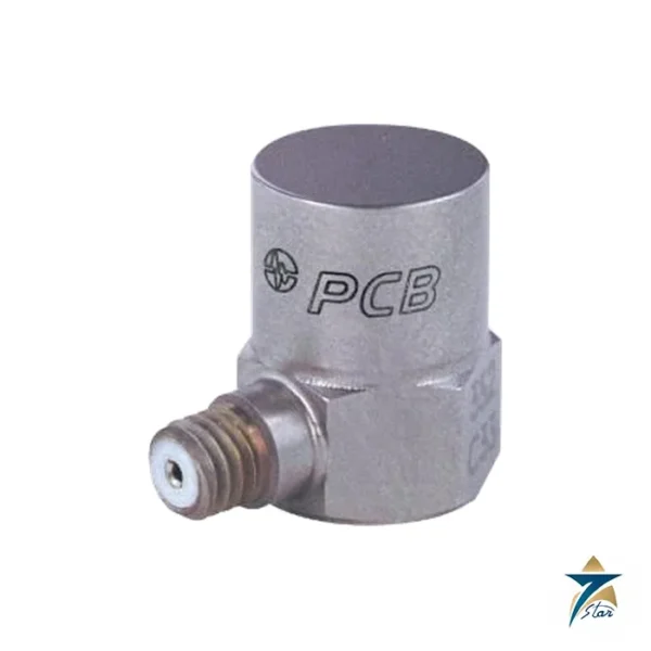
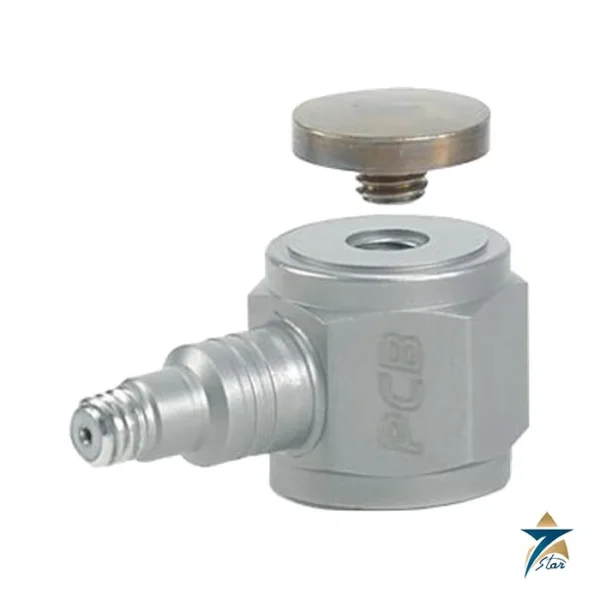
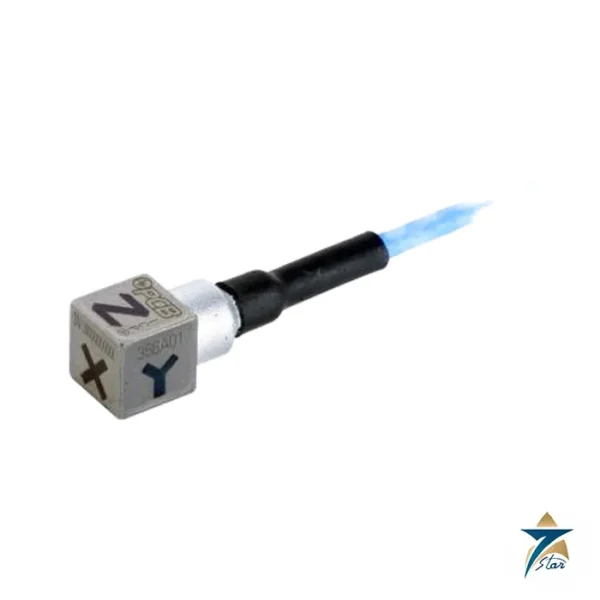
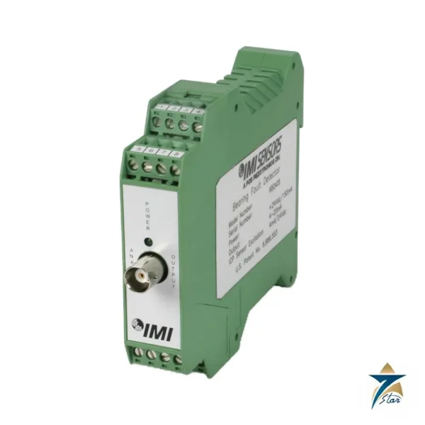
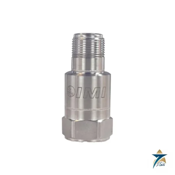
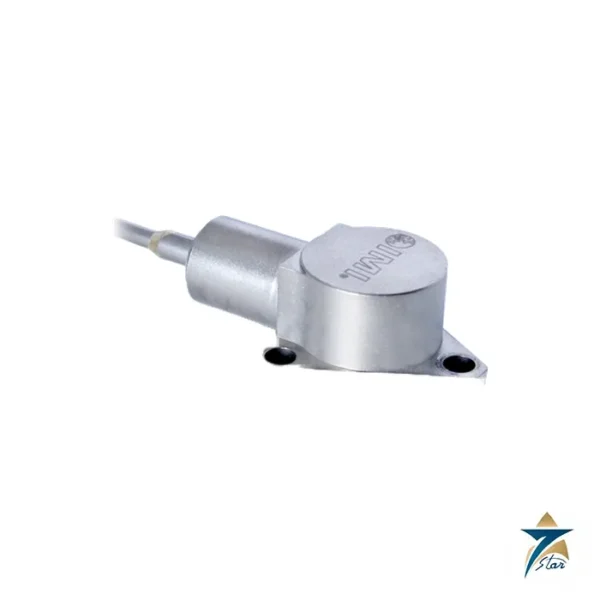
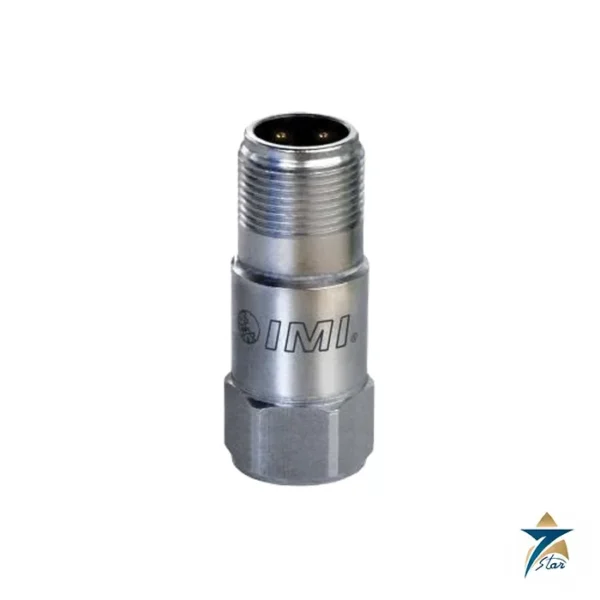
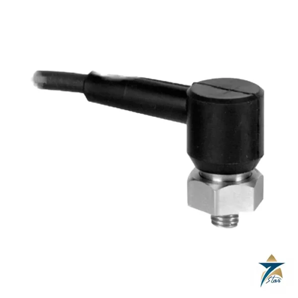
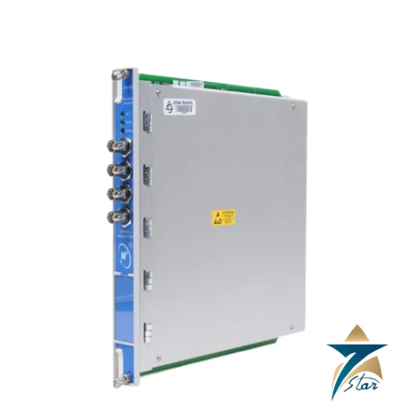
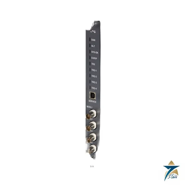
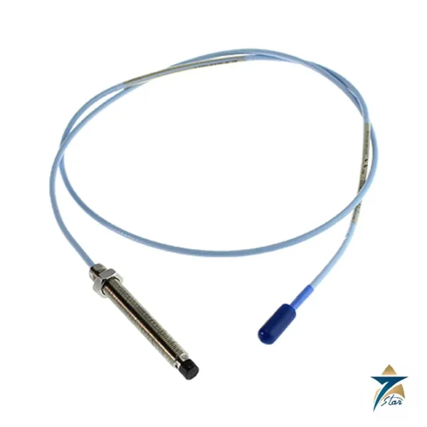
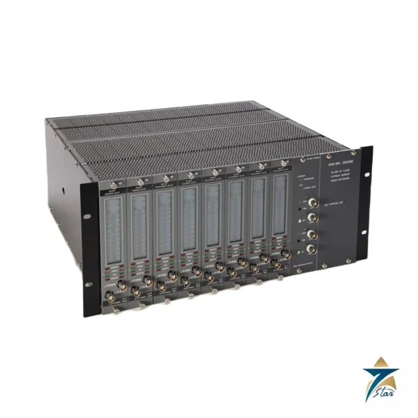
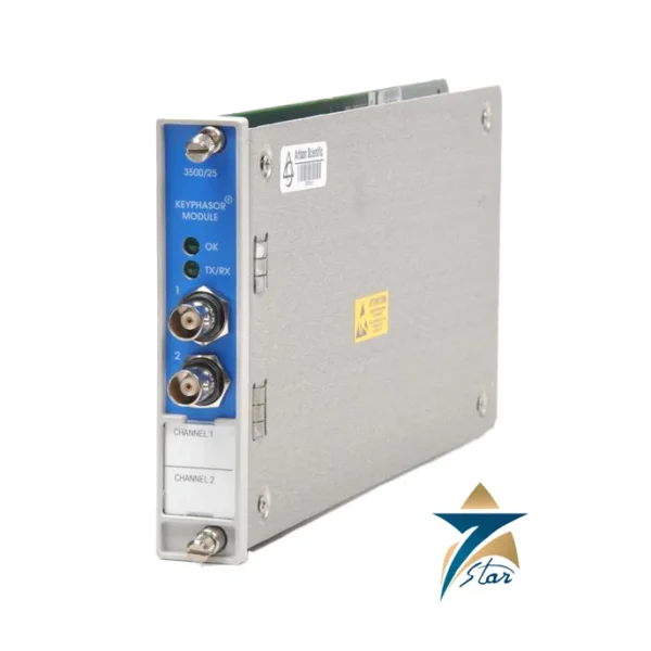
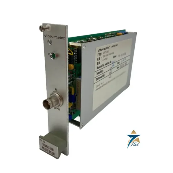
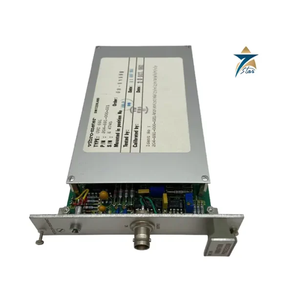
Check that 0 to 1 in/sec and 3 to 1,000 Hz match your alarm limits and machine speed, whether you need the RV or EX option, and the mating cable. The picture on the manufacturer page is a series image, so check the received part number. See also the PCB Piezotronics 640B01 velocity transmitter.
How the PCB Piezotronics 642A01 works
Inside the 642A01 a ceramic element works in shear. When the machine vibrates, the element produces a charge that is proportional to acceleration. Electronics inside the welded stainless steel housing integrate the signal to velocity and convert it to a current between 4 and 20 mA. The full scale of 20 mA stands for 1 in/sec peak, or 25.4 mm/s peak. Because the signal is a current, it does not lose accuracy over long cable runs and it can be read by any standard analog input.
Where the 642A01 is used
- Pumps, fans and blowers that need simple vibration trending
- Motors and gearboxes with a PLC or DCS input available
- Cooling tower and compressor monitoring
- Plants without a dedicated machinery protection system
- Alarm and trip inputs on rotating equipment
Selection checklist for the 642A01
- Full scale needed, 1 in/sec peak here, against the vibration levels of the machine
- Frequency range of 3 to 1,000 Hz, and the running speed of the machine
- Loop supply of 12 to 30 VDC
- Temperature range of -40 to 85 degrees C
- Hazardous area approval, the EX option, which needs a factory enquiry
- Metric mounting, the M option, or the RV buffered output option
- Cable and connector, the 2-pin MIL-C-5015 side exit
Installation, commissioning and maintenance notes
Mount the sensor on a smooth, flat surface that is drilled and tapped, and put a thin layer of silicone grease on the interface. Fit it with the supplied stud at the stated torque, which must be higher than the nut torque so that the sensor can be removed. Wire pin A as the positive and pin B as the negative of the loop. Wait for the settling time of under 15 seconds before reading. Compare the first readings with a portable analyser to confirm the scaling, and record the baseline.
Requesting a quotation for the PCB Piezotronics 642A01
Please send the model, the options, the cable length and the quantity. Seven Star LLC serves industrial customers in Oman and the GCC and replies with a quotation based on the information provided.
642A01 low frequency behaviour
Below 5 Hz the current fluctuates, so the sensor is best used on machines that run above 180 cycles per minute.
642A01 resolution and linearity
The typical broadband resolution is 0.005 in/sec peak (0.13 mm/s peak) and the non-linearity is plus or minus 1 percent.
642A01 construction
The sensor has an IP68 rating, a hex of 7/8 inch and a height of 1.41 inch. It weighs 108 g and has a 1/4-28 UNF mounting thread.
642A01 calibration
The sensor is calibrated before shipment, and the ICS-4 single-axis calibration covers 0 Hz to the upper limit of the frequency range.
Sensor records for 642A01
Keep the tag, the location, the baseline reading and the alarm settings with the machine file.
Documents and quotation
The PCB installation and operating manual for the 642A01 is attached; its spec sheet is rev G. Seven Star LLC is an independent supplier in Muscat. More products: Vibration Monitoring.









Reviews
There are no reviews yet.