- Automation & ControlView all 1,996 products
- AC Drives
- PLC & I/O Cards
- Industrial Communications
- Automation Accessories
- Vibration Monitoring
- Controllers & Data Acquisition
- Isolator & Barrier
- CCTV & Security
- Safety Switches & Guard Locking
- Encoders
- HMI Displays
- Motor Soft Starters
- Industrial Computers
- Pneumatic Cylinders
- Servo Drives
- Machine Vision
- Automation Software
- Robotics
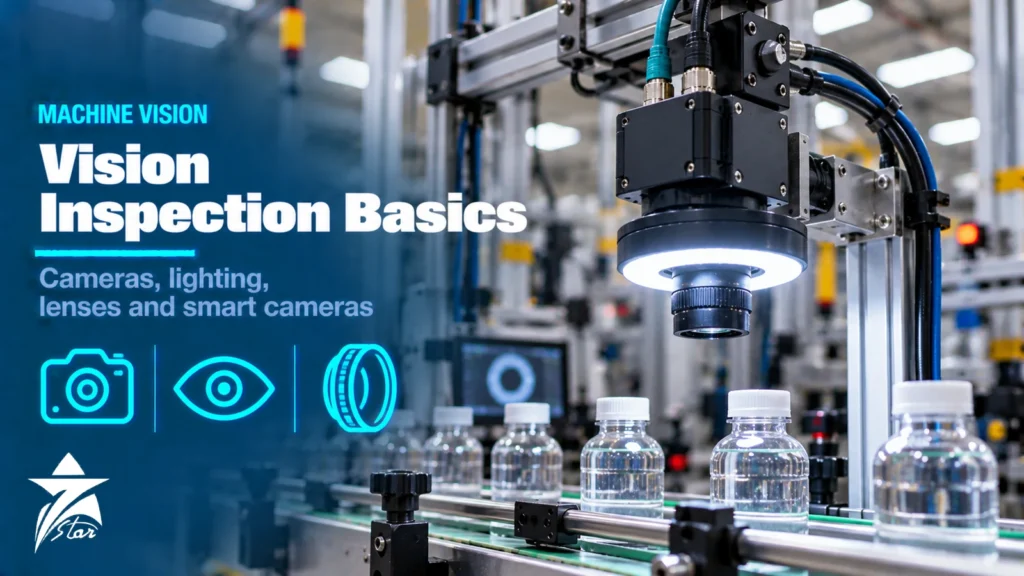
A machine vision inspection system uses cameras, lighting, optics and software to check parts automatically on a production line: verifying presence and position, measuring dimensions, reading codes and finding surface defects. A well-designed system inspects every part at line speed and gives consistent results, while a poorly designed one generates false rejects and is switched off within weeks. Most of the difference comes from decisions made before any software is configured: what exactly must be detected, how many pixels that needs, how the part is lit and presented, and which processing platform fits the task. This guide walks through those decisions.
Define the Inspection Task First
Write down the inspection requirement in measurable terms before choosing hardware:
- Task type: presence or absence, position and orientation for robot guidance, measurement, code reading or OCR, colour checks, or surface defect detection.
- Smallest feature or defect that must be detected, and the tolerance for measurements.
- Field of view: the area that must be covered, plus a margin for part position variation.
- Speed: parts per minute or line speed, and the time available for each inspection.
- Part variation: materials, colours, reflective or transparent surfaces, and how much the appearance changes between batches.
- Output: pass or fail signals, reject actuation, data to a PLC or MES, images for traceability.
Collect real good and bad samples. A feasibility test with actual parts is the fastest way to confirm whether the defect can be seen at all.
Camera Types and Sensors
| Choice | Options | When it matters |
|---|---|---|
| — | — | — |
| Scan type | Area-scan or line-scan | Line-scan for continuous web or rotating cylinders |
| Colour | Monochrome or colour | Monochrome gives better resolution and sensitivity; colour only when colour is the feature |
| Shutter | Global or rolling | Global shutter avoids distortion of moving parts |
| Resolution | From VGA to many megapixels | Driven by field of view and smallest feature |
| Frame rate | Frames per second at full resolution | Must match line speed with margin |
| Interface | GigE Vision, USB3 Vision, CoaXPress, Camera Link | Cable length, bandwidth and number of cameras |
Most modern industrial cameras use CMOS sensors. GigE Vision cameras can run on standard Ethernet cabling up to 100 m and can be powered by PoE, which simplifies installation. USB3 Vision offers high bandwidth with short cables, and CoaXPress or Camera Link serve very high data rates. The GenICam standard provides a common programming interface across cameras from different manufacturers.
Sizing Resolution and Field of View
Resolution is set by the field of view and the smallest feature:
- Determine the field of view in each direction, for example 120 mm by 90 mm.
- Decide how many pixels must cover the smallest feature: typically about 3 to 5 pixels for detection and more, often 10 or above, for measurement with tight tolerances.
- Calculate pixels needed: field of view divided by feature size, multiplied by pixels per feature. For a 0.5 mm defect with 4 pixels across it in a 120 mm field, you need 120 / 0.5 x 4 = 960 pixels horizontally.
- Repeat for the vertical direction, then choose a sensor that meets both with some margin.
Higher resolution is not free: it reduces frame rate, increases processing time and data volume, and needs better lenses. If one camera cannot cover the area at the required resolution, consider two cameras or a line-scan camera.
Lighting Techniques
Lighting creates the contrast the software works with, and it is usually the most important design decision. Common techniques:
- Backlight: the part is between the light and the camera, giving a sharp silhouette. Ideal for outline measurement, hole detection and level checks in transparent containers.
- Ring light: mounted around the lens for general, even illumination of flat, matte parts.
- Bar and spot lights at low angle (dark-field): light grazes the surface so scratches, embossing and edges appear bright on a dark background.
- Diffuse dome: surrounds the part with even light to suppress glare on curved, shiny or foil surfaces.
- Coaxial (on-axis) light: illuminates through a beam splitter along the camera axis, useful for flat reflective surfaces and engraved marks.
- Structured light and laser lines: project a pattern or line for 3D height measurement.
Wavelength also matters. Red light is common and works well with monochrome sensors, blue light can improve contrast on some metals and small features, infrared can see through some coloured plastics and reduces the effect of ambient light, and ultraviolet makes fluorescent markings or adhesives visible. Polarising filters on the light and lens reduce glare. Strobing the light in sync with the camera freezes motion and lets the light run brighter without overheating.
Shield the inspection area from ambient light, especially sunlight through doors and windows, which can change throughout the day.
Lenses and Optics
The lens determines the field of view, working distance, sharpness and distortion.
- Mount: C-mount is the most common for industrial cameras; S-mount (M12) is used on compact cameras and smart cameras; larger sensors may need F-mount or M42 lenses.
- Focal length: for a standard lens the field of view is roughly the sensor size multiplied by the working distance divided by the focal length. Use the manufacturer’s calculator to confirm, especially at short distances.
- Image circle: the lens must cover the full sensor, or the image corners will be dark.
- Resolution: high-resolution sensors with small pixels need lenses rated for that pixel size.
- Aperture and depth of field: closing the aperture increases depth of field but needs more light.
- Telecentric lenses: constant magnification over a range of distances and no perspective error, ideal for precise measurement.
- Locking: use lenses with locking screws for focus and aperture so vibration and handling do not change the setting.
Smart Cameras vs PC-Based Vision Systems
Vision sensors are the simplest option: a compact device with built-in lighting and a limited set of tools for presence, pattern or code checks, configured with a few clicks.
Smart cameras combine the image sensor, processor, software, I/O and communication in one housing. They suit single-point inspections, are configured with a graphical tool, connect directly to PLCs over Ethernet-based protocols and keep the system compact.
PC-based systems connect one or more cameras to an industrial computer running vision software or a custom application. They provide more processing power for high resolution, multiple cameras, 3D and deep learning, and more flexibility in software, at the cost of more hardware, integration and long-term software maintenance.
A simple rule: start with a smart camera if the task can be solved with one camera and standard tools; move to a PC-based system for multiple cameras, high data rates, complex algorithms or deep learning.
Rule-based tools, deep learning and 3D
Traditional rule-based tools, such as edge detection, blob analysis, pattern matching, calipers and code readers, are fast, predictable and easy to validate, which makes them the first choice for measurement, alignment and code reading. Deep learning tools learn from labelled example images and handle variable defects, natural products and cosmetic flaws that are hard to describe with rules, but they need a representative image set covering normal variation and each defect type, and their decisions are harder to explain. 3D vision, using laser triangulation, structured light or stereo cameras, adds height information for volume checks, bin picking, weld bead inspection and flatness measurement. Many practical systems combine these approaches in one inspection sequence.
Integration with PLCs and Line Control
The vision system needs a trigger, usually a photoelectric sensor or a position from the line controller, and it must send results in time for the reject mechanism. Most smart cameras support Ethernet-based protocols such as PROFINET, EtherNet/IP and Modbus TCP, plus digital I/O. For line-scan cameras and moving parts, an encoder signal synchronises acquisition to conveyor speed. Plan the timing: trigger, exposure, processing, result and reject must fit within the gap between parts. The vision results are often stored with images for traceability, which links into plant data systems; see our article on Industry 4.0 and smart factories in Oman.
Machine Vision Inspection: Installation and Maintenance Tips
- Mount cameras and lights rigidly, away from vibration sources, with fixed reference positions.
- Present parts consistently with guides or fixtures; the less position variation, the simpler the inspection.
- Protect optics with windows or air knives in dusty or splash areas.
- Keep reference images and a set of known good and bad parts to verify the system after changes.
- Back up the configuration and record lens settings, light settings and working distances.
- Recheck performance after product changes, lighting replacement or line modifications.
Operating in GCC Conditions
Heat and dust affect vision systems in Oman and the GCC. Cameras and LED lights have maximum operating temperatures, and their life and stability decrease when they run hot, so allow for cabinet cooling or enclosures where needed. Dust on lenses and protective windows reduces contrast gradually, so include cleaning in routine maintenance. Bright sunlight near loading doors can overwhelm the inspection lighting; use enclosures, filters and strobed lighting.
Machine Vision Project Checklist
- Inspection task, smallest feature and tolerance defined
- Good and bad samples available for testing
- Field of view, working distance and required resolution calculated
- Camera type, colour or monochrome, shutter, frame rate and interface chosen
- Lighting technique and wavelength confirmed by testing
- Lens focal length, image circle and resolution checked
- Processing platform: vision sensor, smart camera or PC-based
- Trigger, timing, reject mechanism and PLC communication planned
- Environmental protection, cooling and cleaning access
- Configuration backup and verification procedure
Code Readers We Supply
These examples cover image-based code reading.
| Product | Type | Where it fits |
|---|---|---|
| Keyence SR-X100 Autofocus 2D Code Reader | Autofocus 2D code reader | Reading codes on products and parts. |
| SICK Lector632 V2D632R-MWMFB4 Image-Based Code Reader | Image-based code reader | Reading codes on conveyors. |
Send the code type, reading distance and line speed through our quote request form.
Sourcing Machine Vision Inspection Components Through Seven Star LLC
Seven Star LLC supplies cameras, smart cameras, lighting and lenses from our machine vision range on request, together with industrial computers and industrial communication hardware, from manufacturers such as Cognex, Keyence, Basler and SICK. We help with selection and cross-checking part numbers, and availability and lead time are confirmed at quotation.
Replacing a camera or planning a new inspection? Send us the model number from the label, or a short description of the part, field of view and defect size, and we will prepare a matched quotation.
Frequently asked questions
How do I calculate the camera resolution needed for an inspection?
Divide the field of view by the smallest feature you must detect, then multiply by the number of pixels you want across that feature. A common rule of thumb is about 3 to 5 pixels for presence or defect detection and more, often 10 or above, for reliable measurement. Do this for both the horizontal and vertical directions and choose a sensor that meets both.
Why is lighting so important in machine vision?
The camera can only analyse the contrast that the lighting creates. The right technique, such as backlighting for silhouettes, dark-field for surface scratches or diffuse dome lighting for shiny parts, can turn a difficult inspection into a simple one. Poor or variable lighting is one of the most common causes of unstable vision systems.
What is the difference between a smart camera and a PC-based vision system?
A smart camera combines the sensor, processor, software and I/O in one housing and is configured for a defined task. A PC-based system uses separate cameras connected to an industrial computer, which offers more processing power, multiple cameras and more flexible software, at the cost of more components and integration work.
When should I use a line-scan camera?
Line-scan cameras build an image one line at a time as the object moves past, which suits continuous materials such as paper, film, metal strip and textiles, or round objects rotated in front of the camera. They need accurate motion synchronisation, usually from an encoder, and strong, uniform line lighting.
What is a telecentric lens used for?
A telecentric lens keeps the magnification constant over a range of working distances and views the object without perspective distortion. This makes it well suited to precise dimensional measurement, although it must be at least as large as the field of view and is larger and more expensive than a standard lens.
Can deep learning replace traditional vision tools?
Deep learning tools are useful for variable defects, natural products and cosmetic inspections that are hard to describe with rules. Traditional tools are still preferred for precise measurement, code reading and alignment. Many systems combine both, and deep learning still depends on good images and a representative set of labelled examples.
Was this guide helpful?One click helps us write better guides for engineers.
Thank you! Glad it helped. Need this equipment for your project? Request a quotation
Thank you. We will use this to improve the guide.