Twelve-step automatic capacitor bank control from a single CT
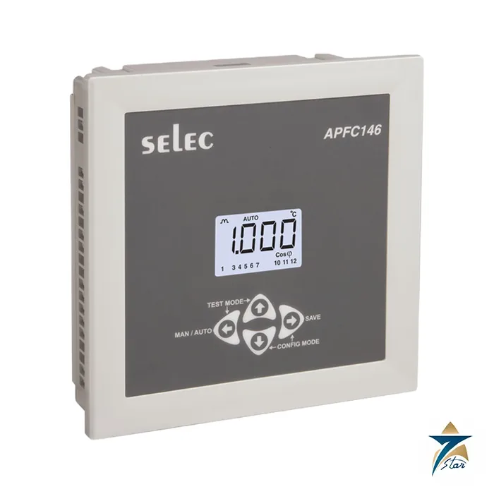
The Selec APFC146-112-90/550V-CE is a 144 x 144 mm automatic power factor controller with twelve normally-open relay outputs for capacitor steps. It senses the load through one CT and a two-wire voltage connection (voltage L2-L3, current L1), so there is no need for a three-CT arrangement, and its intelligent switching sequence chooses the steps that reach the target power factor with the shortest reaction time and the fewest switchings.
Setting up is meant to be quick: the front keys give a target power factor from 0.8 lag to 0.8 lead, a step count of 1 to 12, a step time and a discharge time of 1 to 999 s each, and an over-temperature trip. Auto-initialisation reads the bank sizes, and a CT correction option fixes reversed S1/S2 wiring.
Datasheet features
- 1-CT sensing and zero programming; 12 relay stages
- Intelligent algorithm that selects steps automatically; automatic capacitor bank switching
- 4-digit display and alarm indications (low current, over temperature)
Technical specification
Measurement and control
| Parameter |
Specification |
| Display |
LCD with backlight, 1 row, 4 digits |
| Rated input voltage |
50 to 520 V (L-L); connection 2-phase 2-wire (voltage L2-L3, current L1) |
| Rated input current |
Nominal 5 A AC; minimum 50 mA, maximum 6 A; burden 20 mOhm; frequency 45 to 65 Hz |
| Accuracy |
Power factor 0.01; temperature 3 degC of full scale |
| Measurement range |
Power factor 0.8 lag to 0.8 lead |
| Target PF |
0.8 lag to 0.8 lead (manual default 1.000) |
| Steps |
1 to 12 (default 12) |
| Step time / discharge time |
1 to 999 s each (manual defaults 15 s and 40 s) |
| Over-temperature setting |
10 to 70 degC (manual default 55 degC) |
| Control mode |
Automatic or manual; test mode checks relays in sequence |
| Settable CT / PT |
CT primary 1 and 2: 5 A to 10 kA; CT secondary 330 mV; PT primary and secondary 100 V to 10 kV |
Outputs, supply and mechanical
| Parameter |
Specification |
| Relay outputs |
12 NO contacts, one common point max fuse 6 A; 5 A at 250 V AC maximum per relay |
| Auxiliary supply |
90 to 550 V AC, 50/60 Hz; up to 15 VA |
| Environment |
Operating 0 to 60 degC; storage -20 to 60 degC; humidity 0 to 95% without moisture consideration |
| Mechanical |
Panel mount; 144 x 144 x 50 mm; cutout 138 x 138 mm; 400 g (datasheet) |
| Alarm / error |
Over temperature alarm; Curr shown when current is below 50 mA |
| EMC printed |
IEC 61326-1; ESD IEC 61000-4-2 level III (8 kV air); surge 2 kV line-earth; CISPR 11 Group 1 Class A emissions |
Order code decoding
The code APFC146-112-90/550V-CE reads as: APFC146 controller, 112 = 12 stages, 90/550V = auxiliary supply range 90 to 550 V AC, 50/60 Hz, CE suffix. The datasheet lists only this code.
Set-up and commissioning notes from OP656-V03
Mount in the panel cutout, push the controller in and secure the rear clamp with the screw in the farthest forward slot. The manual also describes a sensor clip assembly for panel or DIN-rail mounting of the temperature sensor.
- Hold the keys for 3 s to enter or leave configuration; 5 s presses toggle auto/manual and start test mode or auto-initialisation (A.INT).
- Run A.INT under stable load; it only works with capacitor banks, not reactors.
- CT reversal correction needs the power factor to be in quadrant I or IV at power-on.
- Use 1.5 mm2 supply wiring and pin-type lugs; vents must not be obstructed.
Why it matters in Gulf distribution panels
Air-conditioning load dominates commercial and residential power in the GCC, so low lagging power factor is common on building incomers and attracts utility penalties or oversizes cables. An APFC panel with a twelve-step controller lets installers split a bank into small and large steps for fine correction. Check capacitor and contactor ratings for harmonic-rich loads; the controller itself only switches the contactors.
What goes with it
Supply a 5 A secondary CT, capacitor contactors, capacitors (or detuned reactor stages), fuses and the optional temperature sensor. Because this unit uses a 330 mV CT secondary setting in its settable list, consult the manual before choosing a CT type.
Selection and installation notes
A power factor controller is selected from the number of capacitor steps, the CT ratio and the network conditions. Mount the CT on the incomer so it sees the total load current, check the phase and polarity relationship between the CT and the voltage tapping, run the automatic set-up so the controller learns the step sizes and set the target power factor to suit the utility tariff. Check the capacitor currents and the step switching after commissioning.
Information needed for a quotation
Send the full model code, the quantity, the delivery location in Oman or the GCC, the intended use and any accessories needed, so that the complete package can be quoted together.
Documents and supply information
The manufacturer data sheet is attached to this page and should be read together with the project specification and the site risk assessment before a purchase is confirmed. Ratings, standards and dimensions are quoted as printed on that sheet. Lead time, stock position and certificates available with the shipment are confirmed in the quotation, and we supply to Oman and the wider GCC region for industrial, utility and building services projects.
Frequently asked questions
How many capacitor steps can it control?
Twelve normally-open relay stages, configurable from 1 to 12.
Which supply voltage range applies?
90 to 550 V AC, 50/60 Hz, consumption up to 15 VA.
How is the CT connected?
One CT on phase L1 with voltage taken across L2-L3, rated 5 A nominal (50 mA to 6 A).
What target power factor can be set?
0.8 lag to 0.8 lead; the manual lists a factory default of 1.000.
Can it protect against over-temperature?
Yes. An over-temperature setting of 10 to 70 degC with an alarm is provided when the sensor is connected.
Documents and quotation
The hosted PDF is the Selec APFC146 datasheet. Please send the bank size, number of steps and CT ratio when you ask for a quote. Check approvals and lead time before ordering. Seven Star LLC is an independent supplier located in Muscat. More products in this range are listed under Electrical & Power.











Reviews
There are no reviews yet.