Thirteen slots for a mid-size ControlLogix system
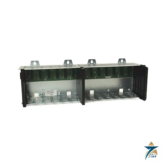
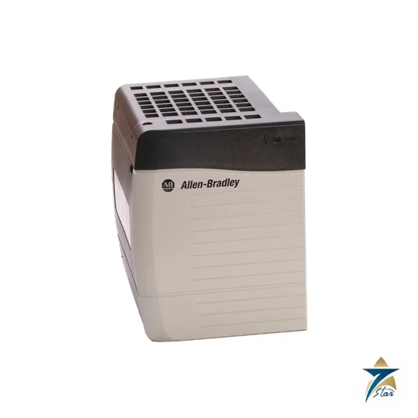
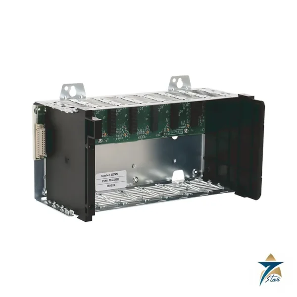
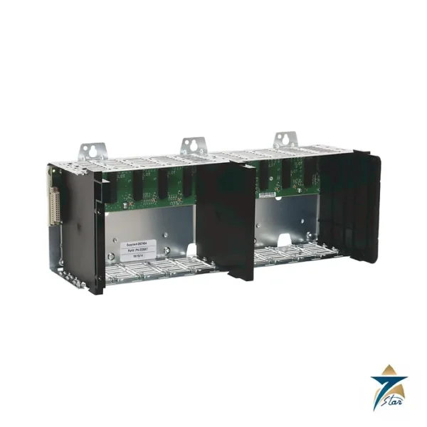
The Allen-Bradley 1756-A13 is the thirteen-slot standard ControlLogix chassis. It sits between the ten-slot 1756-A10 and the seventeen-slot 1756-A17 and is the usual choice when a controller, two or three communication bridges and a block of mixed I/O must share one backplane without moving to a second rack. The backplane carries power and a high-speed communication path to every module, and the power supply fits on the left-hand side of the chassis.
Rockwell Automation publishes a single technical-data table for the A4, A7, A10, A13 and A17 chassis. Only a few lines change from size to size, and for the A13 these are the slot count, the 5.4 W maximum power dissipation, the 1.90 kg weight and the minimum cabinet width of 81.3 cm.
Technical specifications
| Parameter |
Specification |
| Catalog number |
1756-A13 (conformal-coated 1756-A13K listed separately; Series B and Series C) |
| Slots |
13 |
| Mounting |
Horizontal panel mounting only |
| Backplane current, chassis / slot, 1.2 V DC |
1.5 A / – |
| Backplane current, chassis / slot, 3.3 V DC |
4 A / 4 A |
| Backplane current, chassis / slot, 5.1 V DC |
15 A / 6 A |
| Backplane current, chassis / slot, 24 V DC |
2.8 A / 2.8 A |
| Power dissipation, max |
5.4 W |
| Minimum cabinet size (H x W x D) |
50.8 x 81.3 x 20.3 cm (20 x 32 x 8 in.) |
| Weight, approx |
1.90 kg (4.2 lb) |
| Isolation voltage |
Determined by the installed power supply and modules |
| Operating temperature |
0 to +60 C |
| Non-operating temperature |
-40 to +85 C |
| Vibration / shock |
2 g at 10-500 Hz / 30 g operating |
| Earth wiring |
Functional earth 8.3 mm2 (8 AWG); protective earth 2.1 mm2 (14 AWG), copper rated 90 C or greater |
| Enclosure / temperature code |
Open-style; IEC T4 |
Layout and system fit
Any ControlLogix module can sit in any slot of the A13, so slots can be planned around wiring rather than module type. The backplane limit is 15 A at 5.1 V DC for the whole chassis and 6 A per slot, which is the figure to check when many high-current modules such as analog and relay cards are installed. The 3.3 V, 24 V and 1.2 V rails have the limits shown in the table, and the data sheet places the isolation rating with the power supply and the modules rather than with the chassis.
Selection and ordering notes
Check that the cabinet is at least 81.3 cm wide, and that the series fits the modules planned: Series C offers the higher temperature capability, while a Series B chassis limits some modules to 50 C. Order the power supply, blanking covers (slot fillers) and cable accessories separately. If corrosive gas is a risk, use the K version or an XT chassis and confirm the exact catalog number. Data was taken from the manufacturer publication and should be confirmed against your project drawings.
For mounting, bolt the chassis flat on a grounded back panel with the long axis horizontal, and land the 8 AWG functional earth and 14 AWG protective earth wires before powering up. Slot fillers should cover every unused position. The data sheet allows storage from -40 to +85 C at 5 to 95 percent non-condensing humidity and shows UL, FM, CE and hazardous-location approvals, so the paperwork for a Zone 2 or Class I Division 2 panel can be assembled from the same publication.
Typical applications for a thirteen-slot chassis
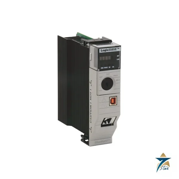
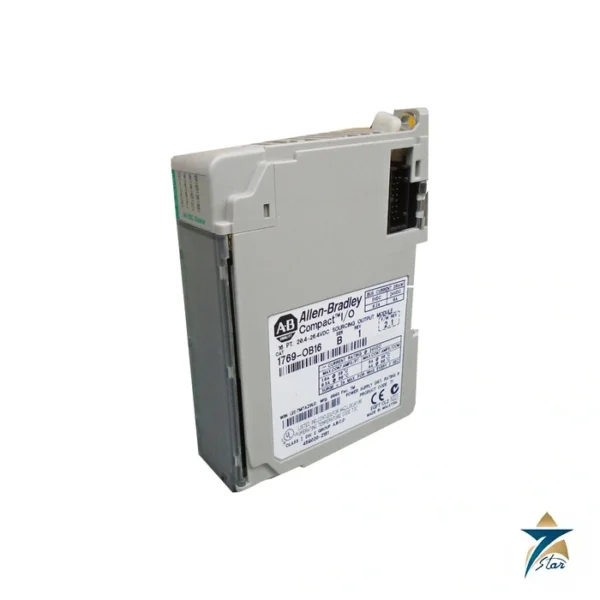
The 1756-A13 is most often found at the heart of a mid-size control system: a process unit, a packaging or production line, a utility plant or a water and wastewater station where one ControlLogix controller handles the logic and a mix of local I/O and communication modules connects it to the rest of the plant. Thirteen slots give room for the controller, the communication bridges needed for the plant network and remote I/O, and a meaningful block of local I/O, while still leaving space for later additions. The same chassis is also used as a remote I/O rack or as a communication rack in larger systems, where the flexibility of placing any module in any slot makes the layout easy to adapt to the field wiring.
Planning the chassis layout
Before ordering, list every module that will sit in the chassis and add up its backplane current at each voltage, then compare the totals with the chassis limits in the table and with the capacity of the chosen power supply. Check the per-slot limit as well for any single module with a high current draw. Group modules in a way that keeps the field wiring tidy: high-voltage and low-voltage I/O are often kept apart, and communication modules are usually placed where their cables can leave the cabinet easily. Leave at least a slot or two free if the system is likely to grow, since that is much easier than adding a second chassis later. If the count already approaches thirteen, compare the A13 with the seventeen-slot A17 before the panel is designed.
Installation and commissioning considerations
Plan the cabinet with the minimum dimensions in the table as a starting point, and allow additional space for wiring ducts, terminal blocks and airflow. Mount the chassis horizontally, as the data sheet requires, and make sure the back panel is properly bonded to earth before the earth conductors are landed. Keep the cabinet within the stated operating temperature range, taking into account the heat from the power supply and modules as well as the chassis itself. During commissioning, verify that each module is recognised in its expected slot, that the slot numbers in the project match the physical layout, and that the power supply is not close to its limit once all modules are running.
How to specify your RFQ
Send the catalog number 1756-A13 or 1756-A13K, the series required, the quantity and the delivery point. If the chassis replaces an existing one, a photo of the label showing the catalog number and series helps us match it. For a new panel, a list of the modules planned for the chassis allows us to point out any obvious mismatch between series and modules before quoting.
Documents and quotation
The linked technical data covers the whole chassis range including XT and ZXT variants. See other PLC hardware in the PLC & I/O Cards category, or send the catalog number to Seven Star LLC, an independent supplier in Muscat, for a quotation.


Reviews
There are no reviews yet.