A slimmer, one-piece base for POINT I/O
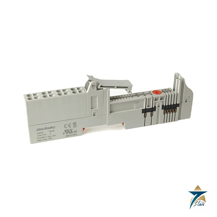
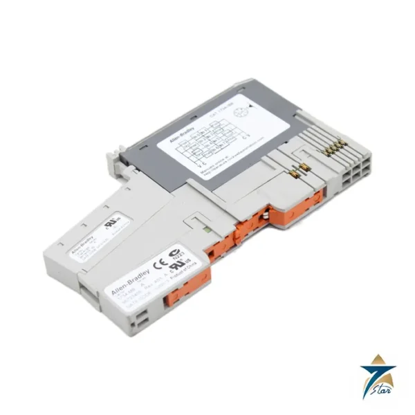
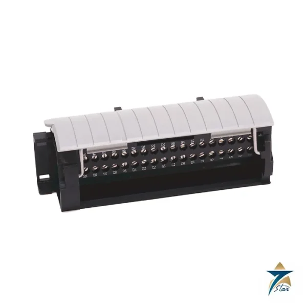
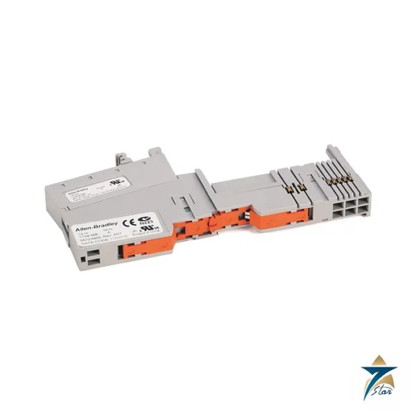
The Allen-Bradley 1734-TOP is a one-piece wiring base for POINT I/O modules. Unlike the two-part 1734-TB assembly, the terminals are part of the base itself, so there is no separate removable terminal block. The result is a lower base, 49 mm high instead of 65 mm, which helps when the enclosure depth or height is tight.
The 1734-TOP uses screw terminals and is the plain version of the family. The 1734-TOPS in the same sheet uses spring clamps, while the 1734-TOP3 and 1734-TOP3S are the longer variants that provide an additional terminal row.
Technical specifications
| Parameter |
Specification |
| Manufacturer / family |
Allen-Bradley (Rockwell Automation) / POINT I/O |
| Catalog number |
1734-TOP |
| Design |
One-piece terminal base with the terminals built in |
| Related catalog numbers in the sheet |
1734-TOPS (spring), 1734-TOP3, 1734-TOP3S |
| Dimensions (H x W x D), approx. |
49 x 12 x 144 mm (1.93 x 0.47 x 5.67 in.) for 1734-TOP and 1734-TOPS |
| Weight, approx. |
63.8 g (2.25 oz) for 1734-TOP |
| Field power bus supply voltage |
28.8V DC, 120/240V AC |
| Field power bus supply current, max |
10 A |
| Signal terminal current |
2 A |
| Isolation voltage |
Capable of 240V (continuous), reinforced insulation type, or the lesser of the installed module |
| Terminal base screw torque |
0.4 N.m (3.5 lb.in), 1734-TOP and 1734-TOP3 only |
| Wire |
Solid or stranded copper rated 75 °C or higher, 1.2 mm insulation max. |
| Enclosure type rating |
None (open-style) |
When to choose it over the 1734-TB
Choose the one-piece base when height matters and you do not need to lift the terminal block off to swap modules. Because the wiring is part of the base, replacing the base means re-terminating the field wires, whereas the 1734-TB lets the terminal block be reused. Many maintenance teams therefore stock the modules and keep the bases for new nodes.
The installation sheet lists the weights as 63.8 g for the 1734-TOP and 79.2 g for the 1734-TOP3, and depths of 144 mm and 168 mm. Both match the same 12 mm module width. If a node already uses two-piece bases, the one-piece type can be mixed in the same node, because the module position and keying are defined by the base and not by the terminal style.
Wiring and installation
Use solid or stranded copper wire rated at 75 °C or higher with insulation not exceeding 1.2 mm. The sheet includes tables of wire size ranges with and without ferrules, and the wire category is determined by the installed module. Tighten the screws to 0.4 N.m for the 1734-TOP.
Mount the base on a grounded DIN rail with end anchors, set the keyswitch to the module position and do not remove a base with power applied. The equipment is open-type and must be installed in an enclosure suitable for the environment.
Selecting the 1734-TOP for a new POINT I/O node
Start the selection from the module list rather than from the base. Each POINT I/O module defines how many field conductors it needs, what wire category applies and how much signal current flows through the terminals, so the base only has to match the module footprint and the terminal count. Where the planned modules fit within the standard terminal row, the 1734-TOP is the compact option; where a module needs extra common or shield connections, the longer 1734-TOP3 with its additional row is the better match.
Decide on screw or spring terminals at the same time. The screw version suits panels where technicians already work with a torque screwdriver and where wires are checked at every shutdown. The spring-clamp 1734-TOPS can be faster to wire in volume, but mixing both styles in one cabinet means two termination methods to train for and inspect.
- List every module in the node and confirm that each is supported by a one-piece base.
- Check that the reduced 49 mm height and 144 mm depth actually solve a space problem in the enclosure before standardising on it.
- Plan the field power distribution so that the bus current stays within the 10 A limit stated for the base.
- Allow spare positions on the rail for later expansion of the node.
Commissioning and inspection routine
Before applying power, walk the rail from the adapter to the end cap and confirm that every base is seated, latched and fitted with the correct keyswitch setting for the module that will sit on it. A wrongly keyed base is easier to correct at this stage than after field wires have been landed. Check that end anchors are tight so that the node cannot slide along the DIN rail and stress the backplane connections.
When landing wires, strip to the length recommended in the installation sheet, use ferrules where the wire size table allows them, and torque each screw to the stated value. Pull-test a sample of conductors on every base. Label each wire at the terminal so that a future base replacement, which on this one-piece design means moving every conductor, can be done without referring back to drawings for each point.
Maintenance and troubleshooting
- Intermittent channel faults: re-check terminal tightness first; vibration from nearby motors and pumps can loosen screw terminals over time.
- Module not recognised: confirm the keyswitch position matches the module and that the module is fully pressed onto the base.
- Discoloured terminals: look for overloaded field power wiring or a poor connection, and review the load against the field power bus rating.
- Damaged base: because the terminals are integral, plan the replacement as a re-termination job and remove power before taking the base off the rail.
Using POINT I/O bases in Oman and GCC panels
The 1734-TOP is open-style equipment, so its protection in the field comes entirely from the enclosure. In Omani plants and outdoor skids, cabinet temperatures in summer can climb well above the ambient air, especially in panels facing direct sun. Shade the enclosure, keep ventilation paths or cooling units clean, and leave space around the node so that heat from the modules can escape rather than build up around the terminals.
Fine desert dust is the other common problem. Dust that settles on terminals and between bases can attract moisture during humid nights, and in coastal locations such as Sohar, Duqm or Salalah that moisture often carries salt. Specify gasketed enclosures with filtered ventilation, keep cable entries sealed, and include a visual check of the POINT I/O terminals in the routine panel inspection. Where corrosion is found on screw terminals, investigate the enclosure sealing rather than simply replacing the base.
For maintenance stock, many sites keep one spare base of each type used in their nodes alongside the spare modules. Since the one-piece design ties the wiring to the base, having a spare on hand shortens a repair to the time needed to move the conductors across.
Documents and quotation
The 1734-IN028 installation sheet describes the one-piece wiring bases. Send the 1734-TOP reference, quantity and the module types that will be fitted, and confirm whether a 12-position or longer base is needed. Related hardware is listed in PLC & I/O Cards.







Reviews
There are no reviews yet.