Power for a bank of Compact I/O modules
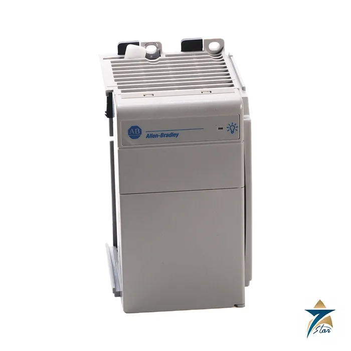
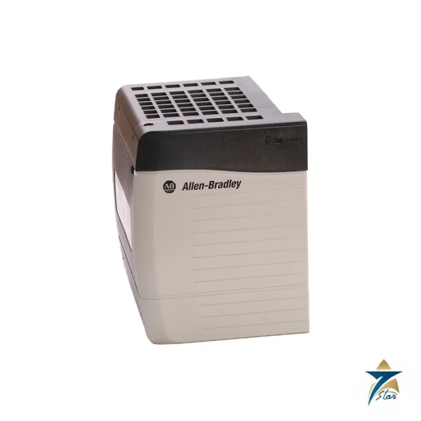
The Allen-Bradley 1769-PA2 is the 2 A AC power supply of the Compact I/O family. It accepts 85 to 265 V AC input and delivers 2.0 A at 5 V DC for the backplane logic and 0.8 A at 24 V DC for the modules, which is enough for a typical bank of digital and analog modules. Each 1769-L3x CompactLogix controller and each additional bank of I/O requires a 1769 power supply.
Place up to eight I/O modules on each side of the supply for a maximum of sixteen. Every module has its own power supply distance rating, which states how many positions it may sit from the supply, so the layout must respect the rating of each module on the rack.
Technical specifications
| Parameter |
Specification |
| Catalog number |
1769-PA2 (1769-PA2K conformal coated) |
| Type |
Compact I/O AC power supply |
| Input voltage range |
85…265V AC; nominal 120V/220V AC |
| Power consumption |
100VA at 120V AC; 130VA at 240V AC |
| Output capacity |
2.0 A at 5V DC and 0.8 A at 24V DC |
| Power dissipation |
8 W at 60 °C (140 °F) |
| Inrush current |
25 A maximum at 132V AC |
| Isolation |
265V continuous, reinforced insulation (IEC Class 1 grounding required); routine tested at 2596V DC for 1 s |
| Fuse type |
Wickmann 19195-3.15A / Littelfuse 02183.15MXP |
| Module capacity |
8 I/O modules on either side of the supply, maximum 16 modules |
| Dimensions / weight |
118 x 70 x 87 mm (4.65 x 2.76 x 3.43 in.); about 525 g (1.16 lb) |
| Wiring |
14 AWG (2.5 mm²) solid copper, rated 90 °C or greater; wire category 1 on power ports |
| Mounting |
DIN rail or panel; mounting screw torque 1.16 N•m (10 lb•in), M4 or #8 screws |
| Operating temperature |
0…60 °C (32…140 °F); non-operating -40…+85 °C; humidity 5…95% non-condensing |
| Vibration / shock |
5 g at 10…500 Hz; operating shock DIN rail 20 g, panel 30 g |
| Temperature code / enclosure |
North American T3C; open-style |
| Larger variants |
1769-PA4 4 A at 5V DC / 2 A at 24V DC; 1769-PB2 and 1769-PB4 for 24V DC input |
Sizing the supply
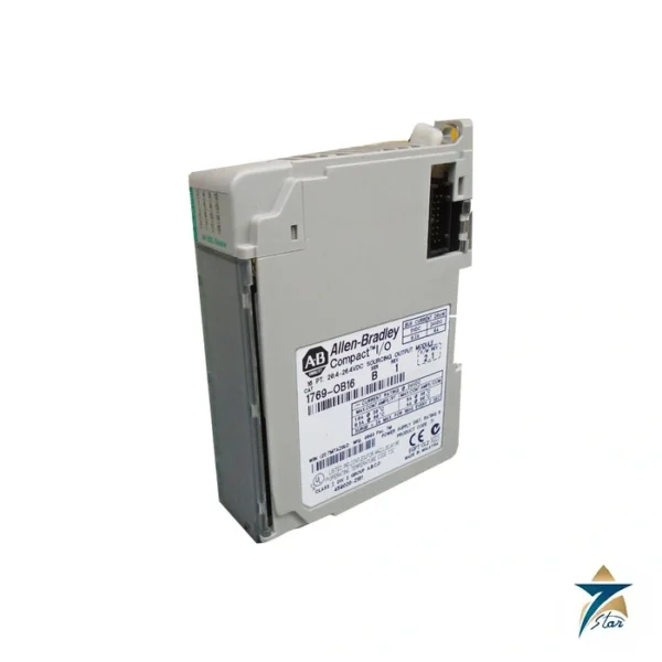
Add the 5 V DC and 24 V DC bus currents of every module in the bank and compare them with the 2.0 A and 0.8 A capacities. The 1769-OF4 draws 170 mA at 24 V DC and the 1769-OF8C 185 mA, so a handful of analog outputs can use most of the 24 V budget. If the total exceeds the capacity, use the 1769-PA4, which gives 4 A at 5 V DC and 2 A at 24 V DC, or split the rack into two banks with a second supply.
Power consumption is 100 VA at 120 V AC and 130 VA at 240 V AC. Inrush can reach 25 A at 132 V AC, so size upstream protection accordingly, and the supply is IEC Class 1 equipment that requires a protective earth connection.
Related supplies
The 1769-PB2 and 1769-PB4 take 24 V DC input instead of AC, and the 1769-PA4 is the 4 A AC version. The supply fuse is a Wickmann 19195-3.15A or Littelfuse 02183.15MXP type. Wire the input with 14 AWG copper rated at 90 °C or higher.
Installing the 1769-PA2 in the rack
Plan the bank on paper before mounting anything. Mark the position of the supply, list the modules to its left and right, and check each one against its power supply distance rating so that no module ends up too far from the supply. Leave space in the layout for future modules where the I/O list may grow, but remember that any addition must still fit within the current budget.
Mount the supply and modules on DIN rail or directly on the panel using the screw size and torque in the table, and lock adjacent units together so that the bus connectors mate fully. Bring the AC feed through a dedicated circuit with suitable overcurrent protection sized for the inrush current, and connect the protective earth before applying power. Keep AC supply wiring away from analog signal cables entering the I/O modules on the same rack.
Power-up and commissioning checks
Before switching on, confirm the input voltage at the terminals is within the 85 to 265 V AC range. Power up the supply with the controller in program mode and verify that the controller or adapter recognises every module in the expected slot. Any module that does not appear may have a bus connection that is not fully engaged.
Record the calculated 5 V and 24 V loads for the bank in the panel documentation. This makes it easy for whoever adds a module later to check quickly whether the 1769-PA2 still has capacity or whether a larger supply or a second bank is needed.
Operating environment in Oman and GCC panels
The supply is open-style equipment and must be installed in a suitable enclosure. In control rooms that lose air conditioning, field kiosks and outdoor panels across Oman and the Gulf, internal temperatures can approach or exceed the upper limit of the operating range. Monitor the enclosure temperature, keep the supply away from heat-producing equipment such as drives and transformers, and provide ventilation or cooling where the measured temperature requires it.
Dust and humidity are the other common problems. Seal cable entries, maintain door gaskets and keep fan filters clean. Where humid sea air enters cabinets at night, condensation can form on cool surfaces, so consider panel heaters or controlled ventilation to keep the air above its dew point.
Maintenance and fault finding
During planned shutdowns, inspect terminals for tightness and signs of overheating, and confirm the input voltage is stable. If the bank shuts down without an obvious cause, check the supply fuse, the AC feed and the total module load before replacing hardware. Note the listed fuse type in the panel documentation so that any replacement uses the correct part.
Documents and quotation
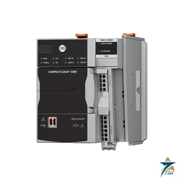
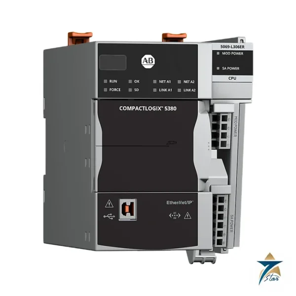
The Rockwell Automation 1769 Compact I/O power supplies technical data is attached. See also our PLC and I/O cards catalogue and the 5069-L320ER controller page. Confirm the exact catalog number, series letter and firmware or hardware revision on the product label, and the compatibility with your existing system, before ordering. Stock and lead time are confirmed at quotation.




Reviews
There are no reviews yet.