A spring-clamp base for vibration-prone POINT I/O nodes
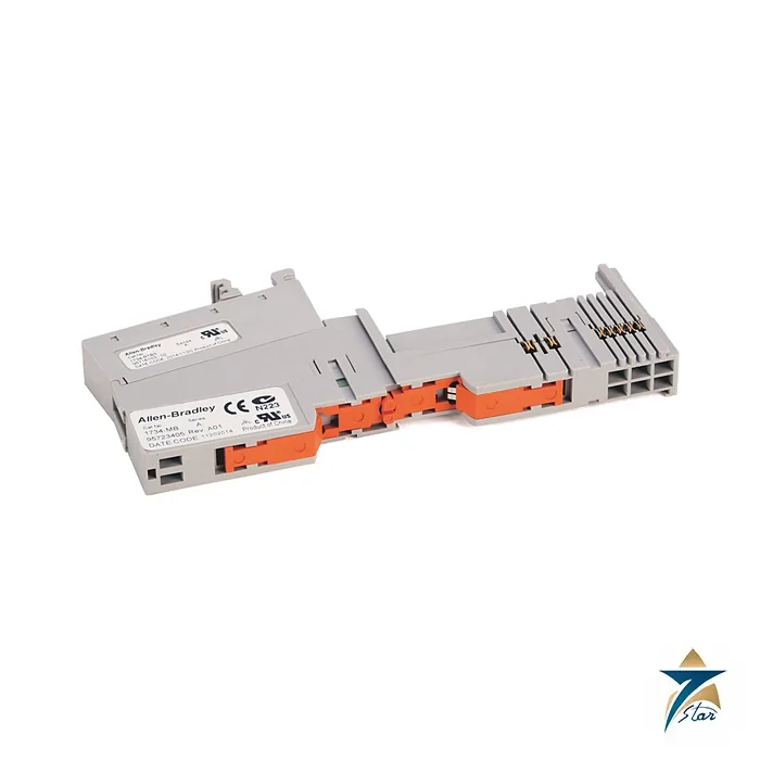
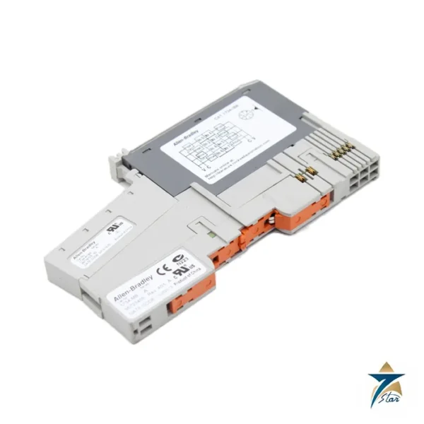
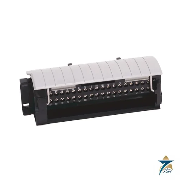
The Allen-Bradley 1734-TBS is the spring-clamp wiring base of the POINT I/O range. It pairs the 1734-MB mounting base with a 1734-RTBS terminal block, so each wire is held by a spring rather than a screw. The module that sits on top is the same as on a screw-clamp base; only the way the field wires are fixed changes.
Spring terminals suit installations where re-tightening screws is awkward or where fast, repeatable wiring is wanted. They are also the lighter of the two standard bases: the manufacturer lists 73.3 g for the 1734-TBS and 83.8 g for the screw-clamp 1734-TB.
Technical specifications
| Parameter |
Specification |
| Manufacturer / family |
Allen-Bradley (Rockwell Automation) / POINT I/O |
| Catalog number |
1734-TBS |
| Assembly |
1734-MB mounting base plus 1734-RTBS removable terminal block |
| Termination type |
Spring clamp |
| Field power bus supply voltage |
28.8V DC, 120/240V AC |
| Field power bus supply current, max |
10 A |
| Signal terminal current |
2 A |
| Wire size without ferrule (1734-RTBS) |
0.08 to 2.5 mm² (28 to 14 AWG) |
| Wire entry tool |
Bladed screwdriver, catalog number 1492-N90 (3 mm blade) |
| Dimensions (H x W x D), approx. |
65 x 12 x 133.4 mm (2.56 x 0.47 x 5.25 in.) |
| Weight, approx. |
73.3 g (2.57 oz) |
| Operating temperature |
-20 to +55 °C (-4 to +131 F) |
| Enclosure type rating |
None (open-style) |
How wires are inserted and released
The installation sheet describes the method. Push a bladed screwdriver (catalog number 1492-N90, 3 mm blade) into the access hole until it stops, push it away from the wire cavity, insert the wire and withdraw the screwdriver. The spring then closes on the conductor. Reverse the sequence to release it.
The published wire range without ferrules is wider on the fine-wire side than for the screw version, down to 28 AWG. Ferrule limits differ again, so check the ferrule tables in the sheet when preparing cable assemblies. Do not wire more than two conductors to a cavity and use only stranded wire if two are fitted.
Mounting and keying notes
Snap the base onto a grounded steel DIN rail and set the keyswitch to the number for the module type before inserting the module. The module can be installed before or after the base, but the field power bus and POINTBus run through every base, so removing one in the middle of a node needs the neighbouring module removed too.
The base is rated for 10 A on the field power bus and 2 A per signal terminal, and the installation category of the wires is determined by the installed module. Spring terminals need no periodic re-tightening, which many maintenance teams prefer on equipment that vibrates. It is open-type equipment for indoor use, which means it belongs in an enclosure with suitable flame-retardant properties.
Key features of the 1734-TBS wiring base
- Two-piece design: the 1734-MB mounting base stays on the DIN rail while the 1734-RTBS removable terminal block carries the field wiring, so a module or terminal block can be changed without disturbing the rest of the node.
- Spring-clamp termination: constant spring force on each conductor, no screws to loosen under vibration or thermal cycling, and no torque values to record during inspection.
- Integrated buses: the base passes both the POINTBus communication bus and the field power bus to the next base, so modules are powered and linked simply by being placed side by side.
- Mechanical keying: the keyswitch on the base is set to match the module type, which helps prevent a wrong module being plugged into a slot already wired for a different signal.
- Narrow 12 mm width: the slim format keeps node length short in crowded marshalling and control cabinets.
Spring-clamp or screw-clamp: choosing the base
The POINT I/O family offers the 1734-TB screw-clamp base and the 1734-TBS spring-clamp base, and both accept the same modules. The choice is mainly about the wiring practice of the site. Spring clamps are faster to wire, accept finer conductors down to 28 AWG and do not need re-tightening, which suits skids, packaged units and machines subject to vibration. Screw clamps are often preferred where the maintenance team works only with screwdrivers and torque checks, or where an existing plant standard specifies them. Mixing both base types in one node is possible mechanically, but a single type per panel keeps spare parts and work instructions simpler.
Module compatibility
The base is used with 1734 POINT I/O digital, analog, specialty and power distribution modules. Some modules occupy more than one base, and some, such as certain communication adapters and power supplies, have their own terminals and do not use a 1734-TBS. Check the user manual of the module you plan to install for the correct base type.
Installation and maintenance practice
- Prepare stranded conductors with ferrules sized to the tables in the installation sheet; use the 1492-N90 screwdriver to open the clamp, not a larger blade that may damage the spring.
- Label each terminal block before removal so it can be refitted to the right slot.
- Remember that the field power bus is segmented by field potential distributors; plan where a new 24 V DC or AC group starts.
- During shutdowns, check that wires are fully inserted and that no insulation is trapped under the clamp.
Applications in Oman and GCC facilities
POINT I/O is frequently used as distributed I/O on EtherNet/IP or DeviceNet in water treatment plants, pumping stations, oil and gas wellhead control panels and packaged process skids. The operating range of −20 to +55 °C covers a well-ventilated or cooled enclosure, but outdoor cabinets in Omani summer sun can exceed that inside the panel, so sunshades, ventilation or panel coolers are usually needed. Because the base is open-type equipment, it must be installed in a closed enclosure that keeps out dust and moisture; this matters in desert sites and in humid coastal areas where condensation forms overnight.
What to include in your RFQ
- Catalog number 1734-TBS and quantity.
- The POINT I/O modules to be fitted, so base count and any additional bases can be checked.
- Whether 1734-RTBS spare terminal blocks or 1734-MB bases are needed separately.
- Delivery location and required date.
Documents and quotation
The shared 1734-IN511 sheet covers both the screw and spring versions. For a quotation please send the 1734-TBS reference, the quantity and the modules that will be fitted, and confirm the wiring style. Related items are listed under PLC & I/O Cards.





Reviews
There are no reviews yet.