Eight safety outputs for contactors and valves
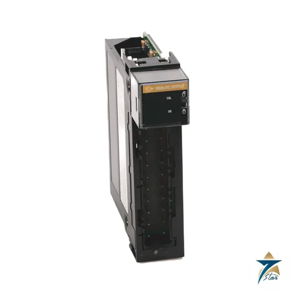
The Allen-Bradley 1734-OB8S is a POINT Guard I/O safety output module with eight sourcing 24V DC outputs. It switches the safety-rated devices of a machine, for example safety contactors, relay coils and valve solenoids, under the control of a GuardLogix, Compact GuardLogix or SmartGuard controller.
It is the output partner to the 1734-IB8S safety input module. The installation sheet places the system, when used as part of POINT I/O, on a safety-control network that meets requirements up to SIL CL 3 and PLe, Cat. 4. As always, the safety integrity of a machine depends on the complete circuit, including the actuators.
Technical specifications
| Parameter |
Specification |
| Manufacturer / family |
Allen-Bradley (Rockwell Automation) / POINT Guard I/O |
| Catalog number |
1734-OB8S (1734-OB8SK is the coated version) |
| Function |
8-channel safety sourcing output module |
| Safety level stated in the sheet |
Up to and including SIL CL 3 and PLe, Cat. 4 (IEC 61508, IEC 61511, IEC 62061, ISO 13849-1) |
| Compatible controllers |
GuardLogix, Compact GuardLogix and SmartGuard |
| Field power |
19.2 to 28.8V DC, 65 mA no load, Class 2, SELV/PELV 150VA max |
| Output voltage |
24V DC |
| Output current |
1.0 A per output at 40 °C; 0.5 A per output at 55 °C |
| Module output current |
8.0 A at 40 °C; 2.0 A at 55 °C |
| Backplane |
5V DC, 125 mA |
| Isolation |
50V continuous, basic insulation between field side and system |
| Indicators |
1 yellow lock status; 1 green/yellow power; 8 I/O channel status |
| Operating temperature |
-20 to +55 °C (-4 to +131 F) |
Current derating and supply
The output rating depends on the ambient temperature. At 40 °C the sheet lists 1.0 A per output with 8.0 A per module; at 55 °C each output is limited to 0.5 A and the module to 2.0 A. Plan the cabinet temperature and the load current together, because a coil that works at 40 °C may exceed the limit at 55 °C.
Field power is 19.2 to 28.8V DC at 65 mA without load, from a Class 2 SELV/PELV supply of at most 150VA. The backplane draws 125 mA at 5V DC. Isolation is 50V continuous, basic insulation, between the field side and the system, and there is no isolation between individual channels.
Fitting the module in a node
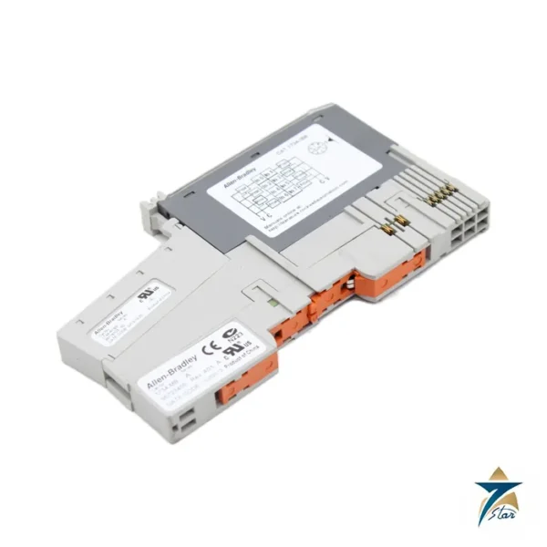
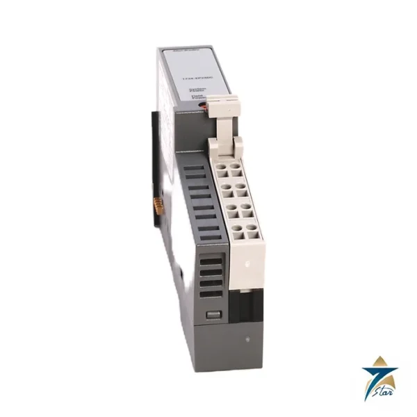
The module is installed on a POINT I/O terminal base using the procedure in the installation sheet, which also shows the removable terminal block. Indicators give lock status, power status and one status LED per channel. The user manual 1734-UM013, cited in the sheet, describes configuration, safety reaction times and diagnostics.
Operating temperature is -20 to +55 °C and the temperature code is T4. Verify the output data and configuration of your own safety function before use; a general product page is not a safety assessment.
Selection checks for the safety output circuit
List every actuator the 1734-OB8S will drive, with its coil current at 24V DC, and add them per output and per module. Compare the totals with the derated limits for the warmest cabinet temperature you expect, not the temperature on the day of commissioning. If the total is close to the 55 °C module limit, spread the loads across more than one output module or reduce the cabinet temperature. Check also that each actuator is suitable for the safety category targeted in the risk assessment; the module alone cannot raise the rating of a device that is not designed for safety duty.
Confirm the controller family and firmware with the user manual 1734-UM013, and decide early whether the 1734-OB8SK coated version listed in the table is needed for the site atmosphere.
Commissioning the safety outputs
After the node is assembled and the module is configured from the safety controller, prove each output individually. Energise one channel at a time with the machine in a safe state and confirm that the correct contactor or valve responds, and only that one. Watch the channel status indicators while doing this so that any mismatch between the drawings and the field wiring is found immediately. Then test the complete safety function: operate the emergency stop, guard switch or light curtain that feeds the logic and confirm the outputs switch off within the reaction time calculated from the user manual.
Record the configuration details, the test results and the date in the machine's validation file. Any later change to the configuration or wiring should be followed by a repeat of the relevant tests.
Cabinet environment in Oman and the GCC
Control panels in Gulf plants are often installed in rooms or outdoor kiosks where summer temperatures approach or exceed the upper limit of the module. Since the output current halves between 40 °C and 55 °C, the cooling of the panel has a direct effect on how many loads the module may switch. Keep panels in shaded, air-conditioned rooms where possible, use panel coolers or filtered ventilation where they are not, and make sure filters are cleaned regularly because blocked filters in dusty areas quickly raise internal temperature.
Fine dust, humidity and in some sites corrosive gases from process or coastal air can affect electronics over time. This is the case where the coated catalogue number mentioned above deserves consideration during design rather than after the first failures.
Maintenance of the safety node
Include the safety function in the periodic proof tests required by the risk assessment. During inspections, check the terminal block for loose wires and signs of heat, verify the field power voltage under load stays inside 19.2 to 28.8V DC, and review controller diagnostics for recurring output faults. When replacing the module, use the same catalogue number and series, and follow the replacement procedure in the user manual so the safety configuration is restored correctly.
Documents and quotation
The installation sheet 1734-IN016 covers four POINT Guard I/O safety modules. Send the 1734-OB8S reference, series, quantity, the safety controller and the load currents when you request a quotation. See also PLC & I/O Cards.



Reviews
There are no reviews yet.