Overview
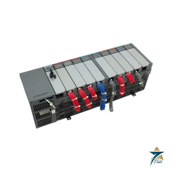
The Allen-Bradley 1746-A10 SLC 500 chassis is the expansion backbone of an SLC 500 system. Its robust backplane and numbered slots make it simple to house a CPU, digital and analog I/O, and communication cards such as DH-485, RIO, and serial bridges.
Choose the 1746-A10 when panel space allows and you want future-proof capacity for machine upgrades or spares consolidation.
Engineering & Design
The chassis provides 10 module positions for the CPU, I/O, and communication modules, with clear slot numbering that simplifies wiring and documentation. The proven 1746 backplane is engineered for 24/7 industrial duty, and each module is held in its slot by top and bottom retainer clips.
Integration is straightforward because the chassis is compatible with standard SLC 500 power supplies and modules, allowing the existing module inventory to be reused when consolidating panels.
Key Features
- 10 module positions
- Robust 1746 backplane
- Modules held by retainer clips
- For CPU, I/O and communication modules
- Clear slot numbering
- Compatible with SLC 500 power supplies and modules
- 24/7 industrial duty
- For upgrades and spares consolidation
Applications
- SLC 500 system expansion
- Panel consolidation
- Machine upgrade projects
- Spare part consolidation
- Legacy control systems
Specifications
| Specification |
Value |
| Manufacturer |
Allen-Bradley (Rockwell) |
| Catalog Number |
1746-A10 |
| Type |
Ten-slot chassis |
| Platform |
SLC 500 |
| Slots |
10 module slots |
| Backplane |
Proven 1746, 24/7 duty |
| Compatibility |
SLC 500 modular processors (SLC 5/01 to 5/05), 1746-P1 to 1746-P7 power supplies and 1746 I/O modules |
| Design |
Numbered slots, six mounting tabs |
| Dimensions with Tabs (W x H x D) |
39.7 × 17.1 × 14.5 cm (15.9 × 6.8 × 5.8 in) |
| Approximate Weight (without modules) |
1.45 kg (3.2 lb) |
| Maximum Backplane Current |
5.1 V DC at 10 A; 24 V DC at 2.88 A |
| Mounting |
Panel mount, 6 mounting tabs, M4 or M5 (#10 or #12) screws |
| Operating Temperature |
0 to +60 °C |
| Storage Temperature |
-40 to +85 °C |
| Relative Humidity |
5 to 95 % (without condensation) |
| System Expansion |
Up to 3 chassis linked, maximum 30 I/O slots |
For SLC 500 expansion, the 1746-A10 SLC 500 chassis is the backbone, and Seven Star LLC supplies the 1746-A10 SLC 500 chassis for your system upgrade.
The Allen-Bradley 1746-A10 is the 10-slot chassis of the SLC 500 system and holds the power supply, the processor and the I/O modules of the controller. The chassis is mounted in the cabinet with the mounting brackets and the modules are inserted in the card guides. The backplane of the chassis distributes the power and the data to the installed modules. The addressing of the I/O is determined by the slot number of the module.
The chassis is supplied without mechanical slot keying, so every slot must be matched in the I/O configuration to the module family. The spare chassis allows the extension of the existing SLC 500 station with the additional module slots. The 1746-A10 is compatible with the SLC 5/01, 5/02, 5/03, 5/04 and 5/05 processors of the family.
The wiring of the chassis is made with the removable terminal blocks of the modules, and the backplane connectors are protected during the module exchange. The replacement of the chassis is performed with the power off and the modules are transferred to the new rack in the same slot order.
The 1746-A10 chassis is ordered with the backplane expansions and the power supply for the CPU of the station. The chassis is mounted on the panel by its six mounting tabs and the ground braid connects the rack to the cabinet ground. Unused slots are covered with 1746-N2 card slot fillers and the spare chassis supports the station extension. The data table and the I/O addressing are documented for the slot assignment of the program.
The 1746-A10 chassis is the standard rack of the SLC 500 control panels and the processor module is installed in the first slot. The backplane supports the communication modules and the programming port of the CPU. The rack is fitted with 1746-N2 card slot fillers in the unused slots for the dust protection of the installed system.
Chassis Interconnect Cables and Expansion Limits
Rockwell Automation allows up to three SLC 500 chassis to be connected for a maximum of 30 I/O slots, so a 1746-A10 can be combined with further racks as long as that total is respected. Three interconnect cables are available: the 1746-C7 is 152.4 mm (6 in) long and is used for chassis mounted side by side, while the 1746-C9 at 914.4 mm (36 in) and the 1746-C16 at 1.27 m (50 in) link one chassis below another. The interconnect cable is installed before the power supply is attached.
The 1746-C9 and 1746-C16 cables have a rigid shrink wrap at each connector for strain relief, and Rockwell asks for at least 101.6 mm (4 in) of clearance at the side of the chassis for them. If the chassis is not linked to another rack, the connector plug stays on the left side connector. Unused slots should be closed with 1746-N2 card slot fillers to keep debris and dust out of the chassis. The modular processor always occupies the left slot, slot 0, of the first chassis.
Mounting and Grounding Notes for the 1746-A10
The 1746-A10 has six mounting tabs and is fixed to the back panel with M4 or M5 (#10 or #12) screws and star washers. Rockwell recommends scraping paint off the panel for electrical contact, and adding washers as shims if the tabs do not lie flat, because a warped chassis can damage the backplane and cause poor connections. Do not drill above a chassis with processor and modules installed, since metal chips can fall into it. The far-left and far-right tabs are left free for the ground connections.
Each enclosure should have a central ground bus. The chassis is connected to the nearest ground bus with 2 mm² (14 AWG) wire kept as short as possible, and the bus is tied to the grounding-electrode system with at least 8.3 mm² (8 AWG) copper wire. Series B chassis have a 1 MΩ resistor between logic ground and chassis ground; when a 1746-P3 power supply is used, the grounding instructions supplied with that power supply must be followed to avoid unwanted potentials on the logic ground of the processor.
Why Seven Star LLC
Seven Star LLC supplies the Allen-Bradley 1746-A10 chassis for SLC 500 systems across the Gulf, with genuine hardware and testing options on request. Our team assists with rack configuration and slot planning for upgrades.
We support maintenance teams consolidating and expanding SLC 500 systems with reliable B2B supply of PLC hardware throughout the GCC.
Installation & Operation
The chassis is mounted in the panel and the power supply and modules are installed in the numbered slots. The clear slot numbering supports the wiring documentation, and the backplane carries the communication between the CPU and modules.
The ten slot capacity provides room for the CPU, I/O, and communication modules of the expanded system.
Request a Quote for 1746-A10 SLC 500 Ten-Slot Chassis
For the 1746-A10 SLC 500 chassis or any related control and instrumentation requirement, contact the Seven Star LLC team. Submit a formal inquiry through our RFQ page with your module, I/O and system configuration, and our specialists will respond with a detailed commercial proposal and the official 1746-A10 documentation.
How to Confirm You Have the Right 1746-A10 Chassis
Before ordering a replacement, read the catalog label on the side or top of the existing rack rather than relying on panel drawings, which are often out of date after years of modifications. The label shows the catalog number (1746-A10 for the ten-slot version) and the series letter. Count the physical slots as a cross-check: SLC 500 racks were also built in four-, seven- and thirteen-slot sizes, and they share the same look, so a photograph of the full chassis with the modules installed is the quickest way for our team to confirm the match.
- Record the catalog number and series from the chassis label.
- Note the power supply catalog number fitted on the left side of the rack.
- List every module and its slot position, starting with the processor in slot 0.
- Check whether the rack is linked to a second chassis with an interconnect cable.
Installation and Commissioning Checklist
A chassis swap is usually done during a planned shutdown, so preparation matters more than the physical work. Save a current copy of the processor program and print the I/O configuration before anything is disconnected. Label each removable terminal block with its slot number so field wiring goes back exactly where it came from.
- Isolate power to the rack and verify it is dead before removing modules.
- Mount the new chassis on the same panel holes and reconnect the ground braid to the cabinet ground bar.
- Refit the power supply, then the modules in their original slot order, pressing each firmly into the backplane connector.
- Reconnect terminal blocks, apply power and confirm the processor goes online without I/O configuration faults.
- Force-free check each I/O point from the field before returning the machine to production.
Maintenance and Troubleshooting
The chassis itself has no active electronics to wear out, so most rack-related problems come from the connectors, the grounding or the environment. Intermittent I/O faults that move between modules often point to a contaminated or damaged backplane connector rather than a failed card. Dust, conductive debris from drilling during panel work and loose ground connections are common causes in field cabinets.
- Inspect backplane connectors for bent pins or discoloration whenever a module is replaced.
- Keep empty slots fitted with filler plates to limit dust ingress.
- Check that the combined current draw of the installed modules stays within the power supply rating when adding cards.
- Re-torque the chassis mounting and ground connections during annual panel inspections.
SLC 500 Systems in Oman and the GCC
Many packaged plants in Oman’s oil and gas, water and manufacturing sectors still run SLC 500 controllers supplied with skids and machines years ago. Replacing a whole control system is rarely justified while the process runs well, so keeping a spare rack and core modules on the shelf is a practical way to protect uptime. High summer temperatures and dust in outdoor shelters make good cabinet ventilation and sealed enclosures especially important for these legacy racks.
Sourcing Through Seven Star LLC
Seven Star LLC helps maintenance teams across Oman and the GCC locate 1746-A10 chassis and matching SLC 500 modules for spares programmes and repairs. Send us the nameplate details and your module list, and we will confirm the part match, condition and lead time before you commit.
Other Models in the Allen-Bradley SLC 500 (1746) System Range
Seven Star LLC supplies models from the Allen-Bradley SLC 500 (1746) System range in Oman and the GCC. Compare the related models below and request a quote for the one that matches your application.
Related Products











Reviews
There are no reviews yet.