The screw-clamp wiring base for POINT I/O modules
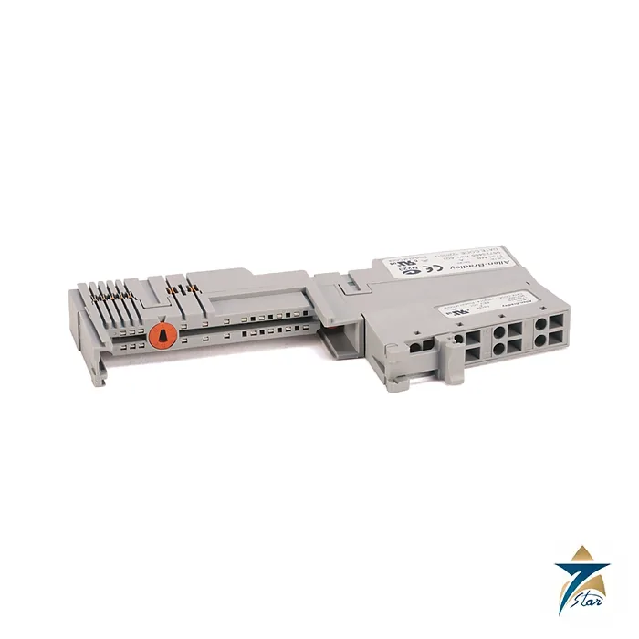
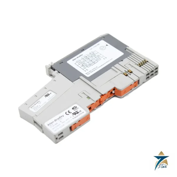
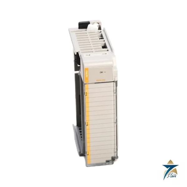
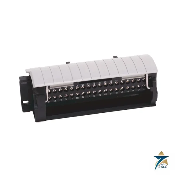
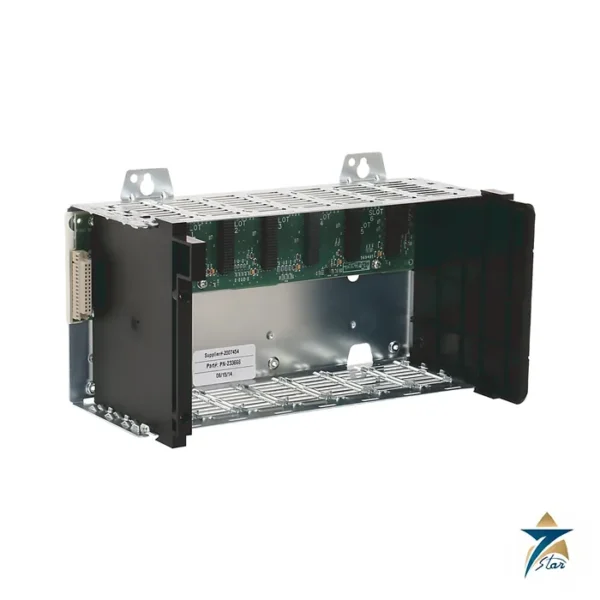
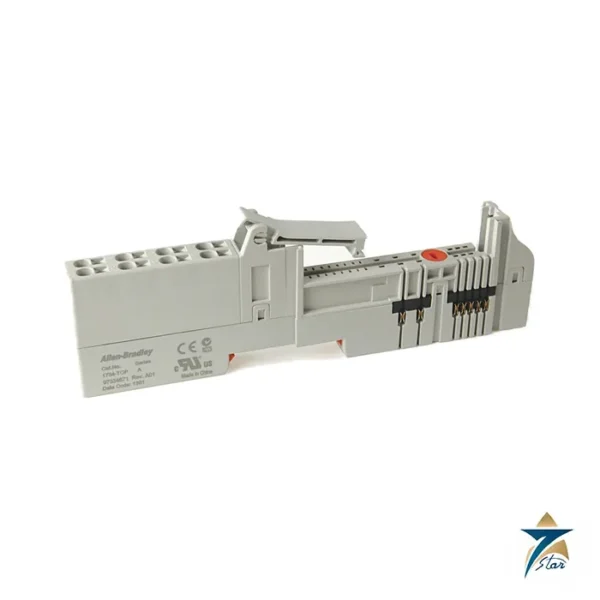
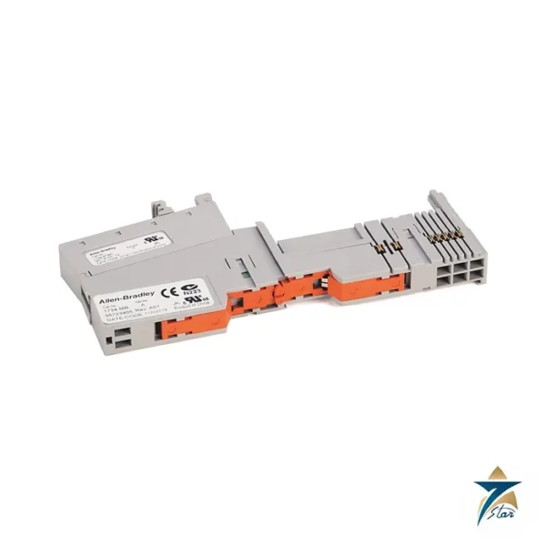
The Allen-Bradley 1734-TB is the wiring base that carries a POINT I/O module and brings the field wiring to it. It is an assembly of two parts: the 1734-MB mounting base, which snaps onto the DIN rail and links the POINTBus backplane and the field power bus from one slot to the next, and the 1734-RTB removable terminal block, which uses screw-clamp terminals.
Because the terminal block lifts off by its handle, a module and its base can be changed without disturbing the field cables. That is the main reason this base is chosen for nodes that are commissioned once and then maintained for years: the wiring stays fixed in the terminal block while the electronics are exchanged.
Technical specifications
| Parameter |
Specification |
| Manufacturer / family |
Allen-Bradley (Rockwell Automation) / POINT I/O |
| Catalog number |
1734-TB |
| Assembly |
1734-MB mounting base plus 1734-RTB removable terminal block |
| Termination type |
Screw clamp |
| Field power bus supply voltage |
28.8V DC, 120/240V AC |
| Field power bus supply current, max |
10 A |
| Signal terminal voltage |
28.8V DC, 120/240V AC |
| Signal terminal current |
2 A |
| Wire size without ferrule (1734-RTB) |
0.25 to 2.5 mm² (24 to 14 AWG) |
| Dimensions (H x W x D), approx. |
65 x 12 x 133.4 mm (2.56 x 0.47 x 5.25 in.) |
| Weight, approx. |
83.8 g (2.94 oz) |
| Terminal base screw torque |
0.8 N.m (7 lb.in) |
| Operating temperature |
-20 to +55 °C (-4 to +131 F) |
| Enclosure type rating |
None (open-style) |
Matching the base to the I/O module
Every POINT I/O module sits on a base, and the base carries a keyswitch with numbered positions that mechanical keying aligns with the module type. The installation sheet shows the keyswitch being turned to the number printed for the module before the module is pressed in. Use the module sheet to find the number, and set it before wiring is energised.
The 1734-TB is the screw-clamp version; the 1734-TBS uses spring-clamp terminals and weighs less (73.3 g against 83.8 g). The two bases are otherwise equivalent in the published field power and signal ratings, so the choice is mostly about how your wiring crew prefers to terminate and how the panel is maintained. The one-piece 1734-TOP family is a separate design with the terminals built into the base.
Installation and wiring points
Seat the mounting base vertically over the DIN rail, slide it down so the interlocking side pieces engage the neighbouring base, and press it home until it snaps. The installation sheet states that the base is grounded through the DIN rail, so use a chromate-passivated steel rail and secure it with end anchors; aluminium or plastic rails can cause intermittent grounding.
Use solid or stranded copper wire rated at 75 °C or higher with insulation not thicker than 1.2 mm. Do not wire more than two conductors per cavity and use stranded wire only when two share a cavity. Never remove or replace a base while power is applied, because interrupting the backplane can cause unintended operation. The base is supplied as open-type equipment for indoor use and must be mounted in a suitable enclosure.
Planning a POINT I/O node with the 1734-TB
Before ordering, draw up the node layout slot by slot. List each I/O module, the keyswitch number it needs, and the field devices that will land on its terminal block. Count the conductors per terminal so you can see where two wires will share a cavity and plan for stranded wire there. Check the total field power bus load against the 10 A limit in the table, and decide where the node needs to be split or fed again so that no section of the power bus is overloaded.
Label each removable terminal block with the slot number and module type at the design stage. Because the 1734-RTB can be lifted away from its mounting base, clear labels make sure a block is returned to the correct slot after maintenance, and the keyswitch setting helps prevent a mismatched module being pressed into place.
Enclosure conditions in Oman and the Gulf
The 1734-TB is open-style equipment rated for -20 to +55 °C, so the enclosure has to keep the rail area within that range. Control panels in Omani industrial sites, pumping stations and utility kiosks can heat up quickly in summer, particularly when they stand in direct sun or sit next to drives and power supplies. Measure the temperature inside the panel near the I/O rail, not just in the room, and add ventilation or cooling if it approaches the upper limit.
Fine sand and dust can collect between terminal blocks and around screw clamps, where it holds moisture and can lead to tracking or corrosion, especially in humid coastal areas. Keep the enclosure closed, use suitable filters on any air inlets and seal unused cable entries. Avoid washing down or blowing dust into the panel with the rail energised.
Terminating field wiring
Strip conductors to the length shown in the installation sheet and make sure no stray strands remain outside the clamp. Tighten each screw to the 0.8 N·m value in the table with a calibrated screwdriver; under-tightened screws can loosen with vibration and thermal cycling, while over-tightened screws can damage the clamp. Separate low-level signal wires from AC field power where the module mix allows, and keep cable routing tidy so terminal blocks can be removed without straining the conductors.
Commissioning and routine checks
Before power is applied, check that every base is fully latched to its neighbour, the DIN rail is anchored at both ends, and each keyswitch matches the module installed. After power-up, verify each channel from the field device to the controller and record the result in the loop check sheet.
During planned shutdowns, inspect terminal blocks for discoloration, loose conductors or signs of heat, re-check screw tightness where the installation is exposed to vibration, and clean away dust with power isolated. Keep a spare 1734-TB on site for critical nodes so a damaged base can be replaced during a planned stop.
Documents and quotation
The wiring-base installation sheet (1734-IN511) holds the wire tables, torque, dimensions and certification data. Send the 1734-TB reference, quantity and the module types it will carry, and confirm the termination style and current ratings before ordering. See also PLC & I/O Cards for related automation hardware.




Reviews
There are no reviews yet.