A 1 MHz counter and encoder module for POINT I/O
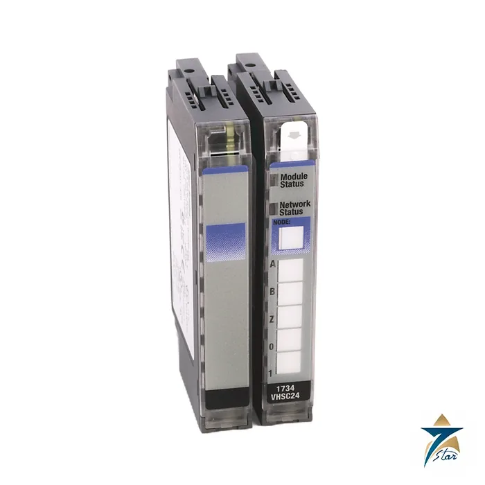
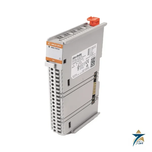
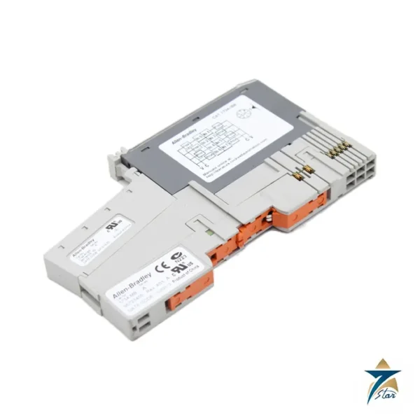
The Allen-Bradley 1734-VHSC24 is a very high speed counter module for the POINT I/O family, for 24 V DC pulse and quadrature encoder signals. One group of inputs (A, B and Z with returns) feeds a counter that handles frequencies up to 1.0 MHz in counter and encoder X1 configurations, with 500 kHz in X2 and 250 kHz in X4 configurations without a filter.
Two outputs on the same module can be tied to four compare windows, so the module can switch a valve or a diverter at a defined count without waiting for the controller scan. The 5 V sibling is the 1734-VHSC5.
Technical specifications
| Parameter |
Specification |
| Catalog number |
1734-VHSC24 (conformal-coated 1734-VHSC24K listed separately; 1734-VHSC5 is the 5 V version) |
| Inputs |
1 group of A/A-return, B/B-return and Z/Z-return |
| Input voltage |
24 V DC |
| Input current |
6.1 mA at 15 V DC; 10.2 mA at 24 V DC |
| Off-state voltage / current |
1.8 V DC max / 0.250 mA max |
| On-state voltage / current |
12.5 V DC min / 5 mA min |
| Input filters |
50 Hz, 500 Hz, 5 kHz, 50 kHz or no filter |
| Maximum input frequency |
1.0 MHz counter and encoder X1; 500 kHz X2; 250 kHz X4 (no filter) |
| Outputs |
1 isolated group of 2, 0.5 A at 24 V DC, linked to 4 compare windows |
| Output supply |
10 to 28.8 V DC |
| Output delay |
25 us off-to-on, 150 us on-to-off (load dependent) |
| Output protection |
Short circuit current 6 A, cycle or latch off by program; open-wire detection when off |
| POINTBus current |
180 mA |
| Power dissipation |
1.9 W (6.5 BTU/hr) |
| Isolation |
50 V continuous basic; tested 1100 V DC for 60 s, field to system |
| Operating temperature |
-20 to +55 C |
| Dimensions / weight |
56.6 x 12.1 x 77.5 mm / 0.03 kg |
Typical applications
Flow metering with pulse output, shaft speed and position feedback, and length measurement are the common uses. The module has no extra external power requirement beyond the field power bus, nominal 24 V with a 10 to 28.8 V range. Filters protect against noise on long cable runs, while the encoder modes support quadrature counting at X1, X2 and X4 multipliers.
Selection and ordering notes
The terminal base (1734-TB, TBS, TOP or TOPS) is ordered separately, and the keyswitch position for the module is 2. The 1734-VHSC24 draws 180 mA from the POINTBus, which is high compared with a digital module, so count it in the adapter current budget. Confirm all values against the installation instructions before purchase. The approvals printed in the document include UL listing for US and Canada (file E65584) and Class I Division 2 Groups A to D (file E194810), CE and UK EMC compliance to EN 61326-1, EN 61000-6-2 and EN 61000-6-4, with temperature codes T4A for North America and T4 for ATEX, UKEX and IECEx. The module is open-style, so install it in a suitable enclosure.
Installing the 1734-VHSC24 in a POINT I/O rack
Fit the terminal base on the rail first, set it to the keyswitch position for this module, and only then insert the module so that it cannot be placed in a base intended for another card. Because the module is open-style, the POINT I/O assembly belongs inside an enclosure that keeps out dust and moisture and that suits the hazardous-area rules of the site where Class I Division 2 or ATEX zones apply. Plan the slot position with the adapter current budget in mind: the 180 mA POINTBus draw of this counter can limit how many further modules the same adapter can feed, so check the total against the adapter rating during design.
Encoder and pulse wiring practice
Use shielded twisted-pair cable for the A, B and Z channels, run each signal with its own return, and keep encoder cables away from motor leads and drive output cables. Ground the shield at one point according to the installation instructions rather than at both ends, which can create ground loops. Check that the encoder or flowmeter output is a 24 V DC type compatible with the on-state and off-state limits of the inputs before connecting it, since a 5 V device belongs on the 1734-VHSC5 instead.
Commissioning the counter and compare outputs
After the module appears in the controller project, configure the counting mode, the X1, X2 or X4 multiplier and the input filter to suit the real signal. Start with the filter that matches the highest expected frequency, then turn the shaft or run the flowmeter slowly and confirm that the count direction and the Z reset behave as expected. Set up the compare windows with safe values first, verify each output switching its valve or diverter with the process isolated, and only then enter production values. Decide whether short-circuit faults should cycle or latch off the outputs, and document that choice for maintenance staff.
Diagnosing count errors
Missing or extra counts usually come from electrical noise, a loose encoder coupling, or a filter setting that is too slow for the actual pulse rate. Compare the counted value with a known movement or a reference volume, check cable shielding and terminations, and review open-wire diagnostics reported by the module before replacing hardware.
Using POINT I/O in hot and dusty GCC plants
The listed operating range ends at +55 °C, and enclosures standing in direct sun in Oman or elsewhere in the Gulf can exceed that inside even when the room air seems acceptable. Place I/O cabinets in shaded or air-conditioned rooms where possible, keep filters on ventilated enclosures clean, and keep doors closed during sand and dust events. In humid coastal sites, watch for condensation when cabinets cool overnight, and inspect terminal bases for corrosion during planned shutdowns. Keeping a record of counter values, fault events and ambient conditions in the cabinet helps the maintenance team link intermittent counting problems to heat or humidity rather than to the module itself.
Documents and quotation
The linked document is the manufacturer installation instruction for the VHSC modules. See related products in PLC & I/O Cards. Send the catalog number and quantity to Seven Star LLC, an independent supplier in Muscat, for a quotation.



Reviews
There are no reviews yet.