Four isolated relay contacts on a 12 mm slice
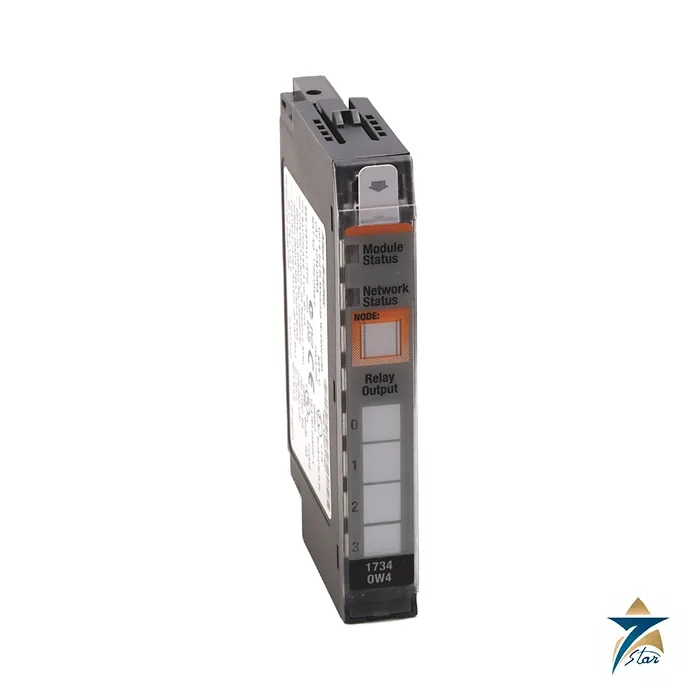
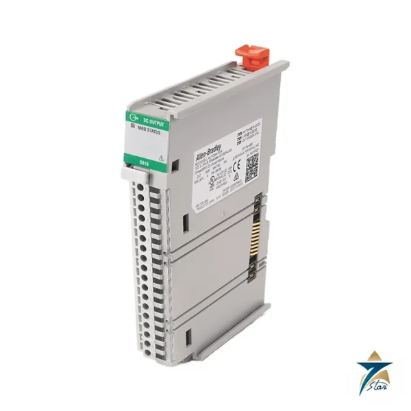
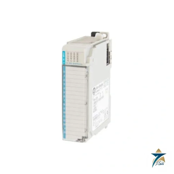
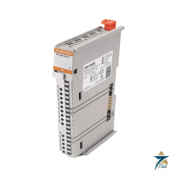
The Allen-Bradley 1734-OW4 is a POINT I/O output module with four Form A, normally open electromechanical relays. Each contact is isolated from the others, so one module can switch mixed circuits, for example a 24 V DC solenoid, a 120 V AC contactor coil and a dry alarm contact, without a separate interposing relay for each load.
The contacts carry 2.0 A at 120 or 240 V AC and 2.0 A at 5 to 30 V DC, with 1800 VA make and 180 VA break capability and a pilot duty rating of R150. Rockwell states a minimum electrical life of 100,000 operations at rated load and a maximum switching rate of one operation every three seconds, so the module is intended for on/off duty rather than rapid cycling.
Technical specifications
| Parameter |
Specification |
| Catalog number |
1734-OW4 (1734-OW4K conformal coated), series D documentation |
| Module type |
POINT I/O 4-point relay output module |
| Outputs |
4 Form A isolated (normally open) electromechanical relays |
| Contact rating |
120/240V AC, 2.0 A at 50/60 Hz; 1800VA make, 180VA break; 5…30V DC, 2.0 A; pilot duty R150 |
| Ex rating note |
Module complies with Ex when used at or below 120V AC |
| Initial contact resistance |
30 mΩ maximum |
| Switching frequency |
1 operation per 3 s (0.3 Hz) at rated load |
| Expected contact life |
100,000 operations minimum at rated load |
| Off-state leakage current |
0 mA; dry contact, no onboard snubbers |
| Backplane power |
5V DC, 90 mA |
| Power consumption / dissipation |
0.8 W consumption; 0.5 W maximum dissipation |
| Isolation |
250V, tested at 2550V DC for 60 s, field side to system and between contact sets |
| Terminal bases |
1734-TB, 1734-TBS, 1734-TOP or 1734-TOPS wiring base |
| Dimensions / weight |
56.6 x 12.1 x 77.5 mm (2.23 x 0.48 x 3.05 in.); 42.5 g |
| Wire size |
0.25…2.5 mm² (22…14 AWG) solid or stranded copper, rated 85 °C or greater |
| Operating temperature |
-20…+55 °C (-4…+131 °F); non-operating -40…+85 °C; humidity 5…95% non-condensing |
| Vibration / shock |
5 g at 10…500 Hz; 30 g operating, 50 g non-operating shock |
| Temperature codes (as printed) |
North American T4A; UKEX/ATEX T4; IECEx T4 |
Applying relay outputs correctly
The relays are dry contacts with no onboard snubbers. For inductive loads such as coils and small motors, fit a surge suppressor across the load, as the manufacturer recommends, because it extends contact life and reduces noise on the control wiring. The Ex compliance note limits use to 120 V AC or less in hazardous-area installations, so check the supply voltage before you apply the module there.
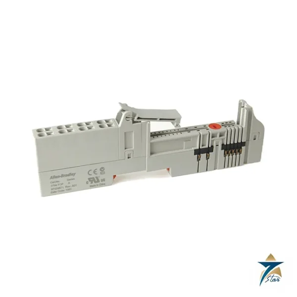
Plug the module into a 1734-TB, 1734-TBS, 1734-TOP or 1734-TOPS base. Because the contact sets are isolated from each other and from the system, each channel is wired to its own load supply.
1734-OW2 and 1734-OW4
The same installation document covers the two-point 1734-OW2, which has two Form A relays and draws 80 mA from the backplane. Choose the OW4 when you want four channels in one slice. For standard 24 V DC sourcing outputs, which switch faster and have no contact wear, use a solid-state module instead.
Installing the module in a POINT I/O rail
Before fitting the 1734-OW4, isolate both the field supplies feeding the relay contacts and the power to the adapter or POINT I/O system. Because every contact set can carry a different voltage, label each terminal with the circuit it switches and the source it comes from, so that a technician working on one channel knows that the neighbouring channels may still be live from another supply. Mount the wiring base on the DIN rail first, check that it is locked into the adjacent bases, and then seat the module so that the backplane connection is complete.
Run mains-voltage load wiring in a separate duct from low-voltage signal and network cabling where the panel layout allows it. Use ferrules or properly stripped conductors within the wire size range listed above, and tighten terminals evenly. When mixed AC and DC loads share the same module, keep the conductors grouped by circuit so that the separation between them is clear during later inspections.
Commissioning and output checks
After the module is recognised by the adapter and the controller configuration, force or toggle each output individually with the load supply disconnected, and confirm with a meter that the corresponding contact closes and opens. Then restore the load supply one circuit at a time and verify that each relay drives the device it is labelled for. Record the channel-to-load mapping in the panel drawings.
Check that the program does not command any output faster than the switching rate stated in the specifications. Logic that pulses an output for flashing beacons or timed dosing may need to be moved to a solid-state output if it cycles more frequently than the relay is rated for. Confirm also that surge suppression is fitted on every inductive load before the system enters normal operation.
Maintenance in Oman and GCC control panels
Electromechanical contacts wear with every operation, so the main maintenance task is monitoring the loads they switch. If a contactor or solenoid begins to chatter, fail to pull in or drop out slowly, check the relay output as well as the field device. Keep a count of operations for heavily used channels where the control system allows it, and plan replacement of the module before it approaches the expected contact life.
Panels in coastal plants, desalination sites and outdoor compounds across Oman and the wider GCC face high ambient heat, fine dust and humid, salty air. Keep the enclosure temperature inside the operating range in the table, using ventilation, filtered fans or cooling as the site requires, and make sure condensation cannot form inside the cabinet when cooled equipment meets humid air. Replace door filters on a fixed schedule, keep cable entries sealed, and inspect terminals for discolouration or corrosion during routine shutdowns.
Selection checks before ordering
Compare each intended load with the contact ratings: voltage, steady current, inrush and whether the load is resistive or inductive. Confirm that the switching frequency of the application suits a relay, that the number of channels matches the I/O list including spares, and that a suitable 1734 wiring base is available or ordered with the module. For hazardous-area panels, verify the Ex limitations described above against the site classification.
Documents and quotation
The Rockwell Automation installation instructions for the 1734-OW2 and 1734-OW4 relay output modules are attached. Related catalogue pages are PLC and I/O cards and the 1734-AENTR dual-port EtherNet/IP adapter. Confirm the exact catalog number, series letter and firmware or hardware revision on the product label, and the compatibility with your existing system, before ordering. Stock and lead time are confirmed at quotation.




Reviews
There are no reviews yet.