Two voltage inputs in a 12 mm POINT I/O slice
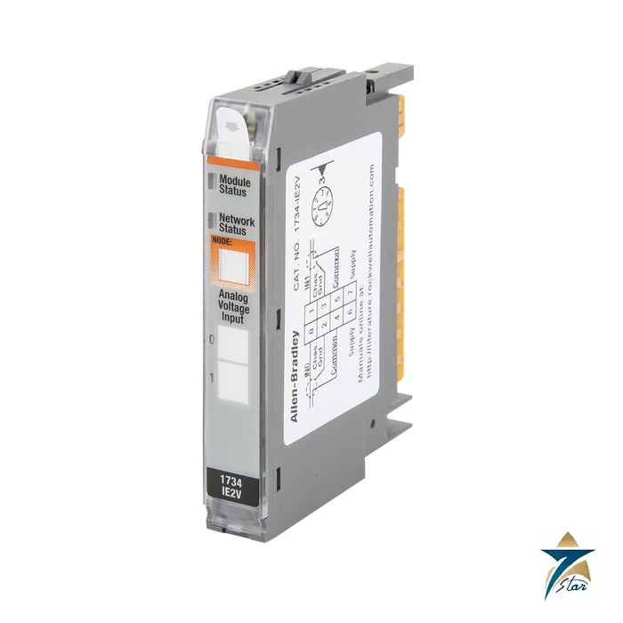
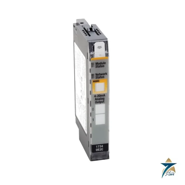
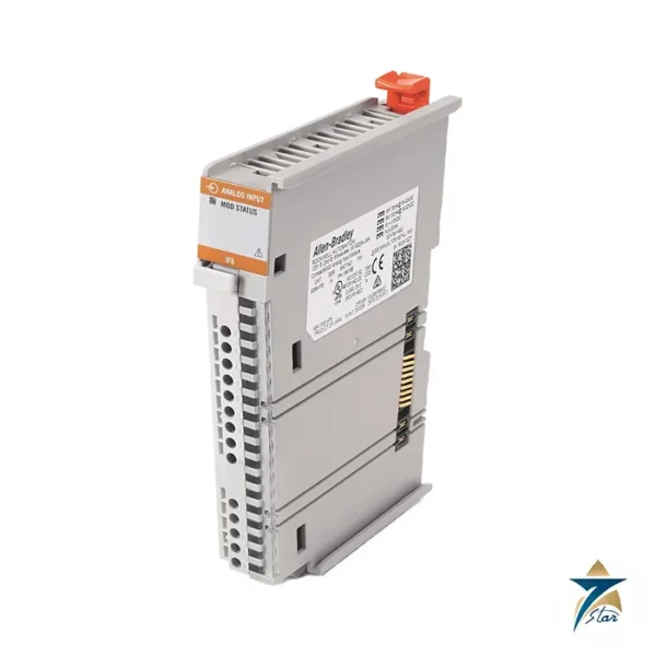
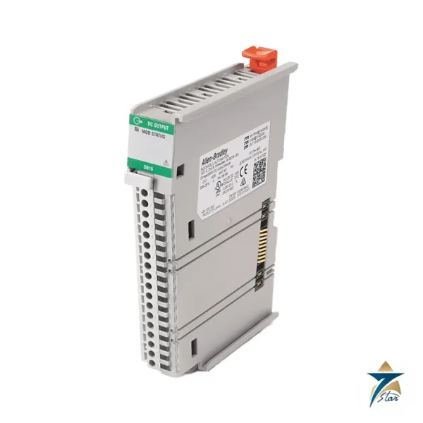
The Allen-Bradley 1734-IE2V is a POINT I/O analog input module that reads two single-ended voltage signals, 0 to 10 V or plus and minus 10 V, and passes them to a Logix controller through a POINT I/O EtherNet/IP or ControlNet adapter. At 12.1 mm wide it adds two channels of 0-10 V transmitter signals to a rail without taking the space of a full-width I/O block.
Resolution is 15 bits plus sign, or 320 microvolts per count, and the manufacturer states an absolute accuracy of 0.1 percent of full scale at 25 °C with a drift of only 5 ppm per °C. A selectable notch filter lets you trade update speed against noise rejection, from 120 ms per module at 50 Hz down to 12 ms at 500 Hz.
Technical specifications
| Parameter |
Specification |
| Catalog number |
1734-IE2V (1734-IE2VK is the conformal-coated version with the same specifications), series C documentation |
| Module type |
POINT I/O 2-point analog voltage input module |
| Inputs |
2 single-ended, non-isolated, voltage |
| Input range |
0…10V user configurable (-0.0V under, +0.5V over) or ±10V user configurable (-0.5V under, +0.5V over) |
| Resolution |
15 bits plus sign, 320 µV per count in unipolar or bipolar mode |
| Absolute accuracy |
0.1% of full scale at 25 °C (77 °F), including offset, gain, non-linearity and repeatability |
| Accuracy drift with temperature |
5 ppm per °C |
| Input update rate (per module) |
120 ms at 50 Hz notch, 100 ms at 60 Hz notch (default), 24 ms at 250 Hz, 12 ms at 500 Hz |
| Step response (per channel) |
80 ms at 50 Hz, 70 ms at 60 Hz (default), 16 ms at 250 Hz, 8 ms at 500 Hz |
| Input impedance / resistance |
100 kΩ / 200 kΩ |
| Filtering |
Digital filter 0…10,000 ms (default 0 ms); common mode rejection 120 dB, normal mode rejection -60 dB |
| Overload protection |
Fault protected to 28.8V DC |
| External DC power |
24V DC nominal, 10…28.8V DC range, 15 mA at 24V DC |
| POINTBus current |
75 mA at 5V DC, maximum |
| Power dissipation |
0.75 W maximum at 28.8V DC |
| Isolation |
50V continuous, tested at 2200V DC for 60 s; no isolation between channels |
| Terminal bases |
1734-TB, 1734-TBS, 1734-TB3, 1734-TB3S, 1734-TOP, 1734-TOPS, 1734-TOP3 or 1734-TOP3S |
| Keyswitch position |
3 |
| Dimensions / weight |
56.6 x 12.1 x 77.5 mm (2.23 x 0.48 x 3.05 in.); about 33 g |
| Operating temperature |
-20…+55 °C (-4…+131 °F); non-operating -40…+85 °C; humidity 5…95% non-condensing |
| Hazardous location marking (as printed) |
North American temperature code T4A; UKEX/ATEX and IECEx temperature code T4 |
Wiring and configuration notes
The module plugs into a terminal base: the one-piece 1734-TOP and 1734-TOPS bases or the two-piece 1734-TB and 1734-TBS family. Each input uses its own signal terminal, a common terminal and a supply terminal; the 24 V DC for sensors is taken from the internal field power bus, and the printed note limits that supply to 0.3 A without protection. Use shielded cable for signal wiring and ground the DIN rail properly, because the module is grounded through the rail.
The module produces 6 bytes of input data, with a status byte per channel that flags overrange, underrange, high and low alarms, calibration mode and channel fault. A flashing red channel indicator means the channel is at the end of its range.
Choosing between voltage, current and thermal inputs
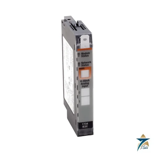
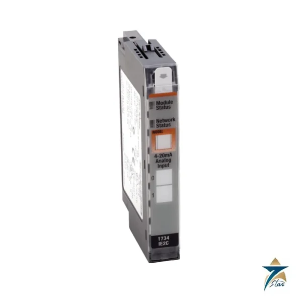
The same installation document covers the 1734-IE2C current input, which reads 4-20 mA and 0-20 mA with 16-bit resolution. Choose the voltage module for 0-10 V instruments and the current module for loop-powered transmitters. For direct temperature sensors use an RTD or thermocouple module. Large analog groups may need a field power module or an expansion supply to keep within the current limits.
Documents and quotation
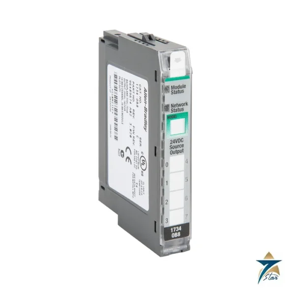
The Rockwell Automation installation instructions for the 1734-IE2C and 1734-IE2V modules are attached and contain the specification tables, wiring diagrams and indicator tables used on this page. See also our PLC and I/O cards range and the 1734-IB8 POINT I/O digital input module. Confirm the exact catalog number, series letter and firmware or hardware revision on the product label, and the compatibility with your existing system, before ordering. Seven Star LLC quotes against the full catalog number; stock and lead time are confirmed at quotation.
How the 1734-IE2V Works
The 1734-IE2V measures each voltage signal against the module common and converts it with a filtered analog-to-digital converter. The notch filter setting decides how long the converter integrates the signal: the 50 Hz and 60 Hz settings strongly reject mains-frequency noise, while the 250 Hz and 500 Hz settings update faster with less rejection. An additional digital filter can smooth noisy process signals further. The result is placed in the input data together with status bits, and the POINT I/O adapter passes it to the controller over the network.
1734-IE2V Selection & Ordering Guide
- Select the 1734-IE2V for 0–10 V or ±10 V signals; for 4–20 mA loops choose the 1734-IE2C.
- Order a compatible terminal base if the module is not replacing one on an existing base.
- Check the adapter backplane current budget and the field power available on the rail.
- Choose the 1734-IE2VK where a conformal-coated module is required.
Our team can help confirm the correct ordering code for the 1734-IE2V when you request a quote.
Installation & Maintenance
Set the terminal base keyswitch to match the module, use shielded cable grounded at one end, and keep signal wiring away from motor and drive cables. Configure the range and filter in the controller project. During maintenance, watch the overrange, underrange and fault status bits and verify readings with a calibrated voltage source.
Typical Applications in Oman & the GCC
- Speed reference and feedback signals from variable-speed drives in pumping stations.
- 0–10 V sensors and actuator feedback in HVAC and district cooling plants.
- Machine and packaging lines using distributed POINT I/O on EtherNet/IP.
Why Source the 1734-IE2V from Seven Star LLC
Seven Star LLC supplies Allen-Bradley POINT I/O modules, including the 1734-IE2V, across Oman and the GCC. Request a quote with the catalog number and quantity.



Reviews
There are no reviews yet.