The largest standard ControlLogix chassis
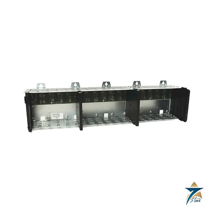
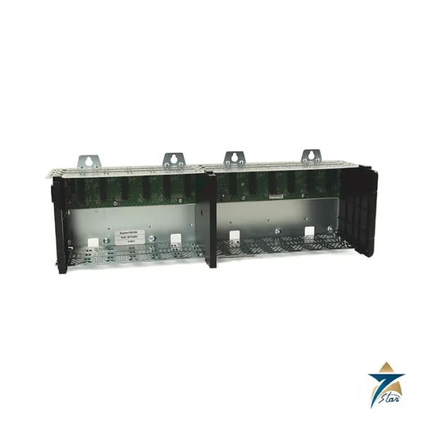
The Allen-Bradley 1756-A17 is the largest standard ControlLogix chassis, with seventeen slots in a single backplane. It is chosen for central control rooms and compressor or power-block cabinets where one controller needs many I/O and communication modules close together, saving the extra cabling and network configuration of a multi-chassis layout.
In the Rockwell Automation table it carries the highest dissipation of the standard range at 6 W, a weight of 2.20 kg and a minimum cabinet width of 96.5 cm, so panel space is the first thing to check. The chassis, power supply and modules are all open-style and need a suitable enclosure.
Technical specifications
| Parameter |
Specification |
| Catalog number |
1756-A17 (conformal-coated 1756-A17K listed separately; Series B and Series C) |
| Slots |
17 |
| Mounting |
Horizontal panel mounting only |
| Backplane current, chassis / slot, 1.2 V DC |
1.5 A / – |
| Backplane current, chassis / slot, 3.3 V DC |
4 A / 4 A |
| Backplane current, chassis / slot, 5.1 V DC |
15 A / 6 A |
| Backplane current, chassis / slot, 24 V DC |
2.8 A / 2.8 A |
| Power dissipation, max |
6 W |
| Minimum cabinet size (H x W x D) |
50.8 x 96.5 x 20.3 cm (20 x 38 x 8 in.) |
| Weight, approx |
2.20 kg (4.8 lb) |
| Isolation voltage |
Determined by the installed power supply and modules |
| Operating temperature |
0 to +60 C |
| Non-operating temperature |
-40 to +85 C |
| Vibration / shock |
2 g at 10-500 Hz / 30 g operating |
| Earth wiring |
Functional earth 8.3 mm2 (8 AWG); protective earth 2.1 mm2 (14 AWG), copper rated 90 C or greater |
| Enclosure / temperature code |
Open-style; IEC T4 |
Layout and system fit
Because every slot is equal, an A17 can hold a controller, redundancy module, several 1756-EN modules, ControlNet bridges and a long run of I/O in whatever order suits the wiring. The backplane can supply 15 A at 5.1 V DC, 4 A at 3.3 V, 2.8 A at 24 V and 1.5 A at 1.2 V in total, and each slot is limited to 6 A at 5.1 V. Large systems usually spread heavier modules so the sum stays within these totals.
Selection and ordering notes
Confirm that the cabinet is at least 96.5 cm wide and that a power supply of adequate capacity is chosen: with seventeen slots the 15 A chassis limit at 5.1 V can be reached, so add the current figures of every planned module. Series B and C chassis are listed, K versions are conformal coated, and XT types are separate catalog numbers. Treat the figures here as a guide and check them against the manufacturer publication and the installed hardware.
A seventeen-slot rack is heavy for its class and wide, so plan the mounting plate, door swing and wireway around the 96.5 cm width. Earthing uses the same conductors as the smaller chassis (8.3 mm2 functional, 2.1 mm2 protective), and unused slots need covers. Storage limits and certification marks are printed in the technical data, which also lists the series B and series C differences, so match them with the modules before purchase.
When a single large chassis is the right choice
A ControlLogix system can be built either around one large chassis or spread across several smaller ones linked by network modules. The 1756-A17 suits projects where most of the I/O and communication modules are concentrated in one panel, such as a central control room, a compressor station control cabinet or a power-block panel. Keeping the controller and modules on one backplane avoids extra chassis, extra network connections and the configuration work that goes with them, and gives maintenance staff a single place to look when diagnosing a fault.
Where the I/O is physically distributed around a plant, or where future expansion is uncertain, smaller chassis connected over EtherNet/IP or ControlNet may be more practical. The decision usually comes down to panel space, cable routing and how the control system is expected to grow over the life of the plant.
Planning the slot layout
Because the chassis is wide, it helps to plan the module order at the design stage. Many engineers group modules by function, for example controller and communication modules together, then analogue I/O, then discrete I/O, so that field wiring enters the panel in a logical sequence. Heavier current users are best spread along the backplane so that the per-slot and total limits in the table are respected, and the power supply budget should be calculated from the published module current figures rather than estimated.
Leaving some slots free for future modules is good practice on new projects, since adding I/O later is easier than adding another chassis and network link once the panel is built.
Installation practice in general terms
The chassis is for horizontal panel mounting inside a suitable enclosure, as stated above. Mount it on a flat, rigid panel so that the backplane is not stressed, and route field wiring through wireways that keep signal and power cables apart. Follow the earthing requirements in the technical data, connecting the functional and protective earth conductors as specified, and check that the enclosure provides the protection required by the open-style rating.
Heat inside the enclosure comes mainly from the power supply and modules rather than from the chassis itself. Plan the cabinet so that the operating temperature range of the chassis and the installed modules is maintained, with adequate spacing around the hardware as described in the Rockwell Automation installation documents.
Considerations for Oman and GCC installations
Control panels in the region often sit in plant rooms, field shelters or packaged buildings where ambient temperatures can be high and dust is common. Placing the panel in a conditioned room or providing suitable enclosure cooling helps keep the hardware within its stated operating range. For sites with corrosive or humid atmospheres, such as coastal facilities, the conformal-coated K version listed in the table can be considered and should be matched with coated modules where the project specification calls for it.
When preparing an enquiry, listing the full set of modules planned for the chassis, together with the required series, allows the chassis, power supply and module combination to be checked against the manufacturer publication before ordering.
Documents and quotation
The linked technical data lists every ControlLogix chassis together. Related automation hardware is under PLC & I/O Cards. For pricing and delivery send your catalog number to Seven Star LLC, an independent supplier in Muscat.




Reviews
There are no reviews yet.