Three-piece self-centring locking assembly for heavy-duty torque
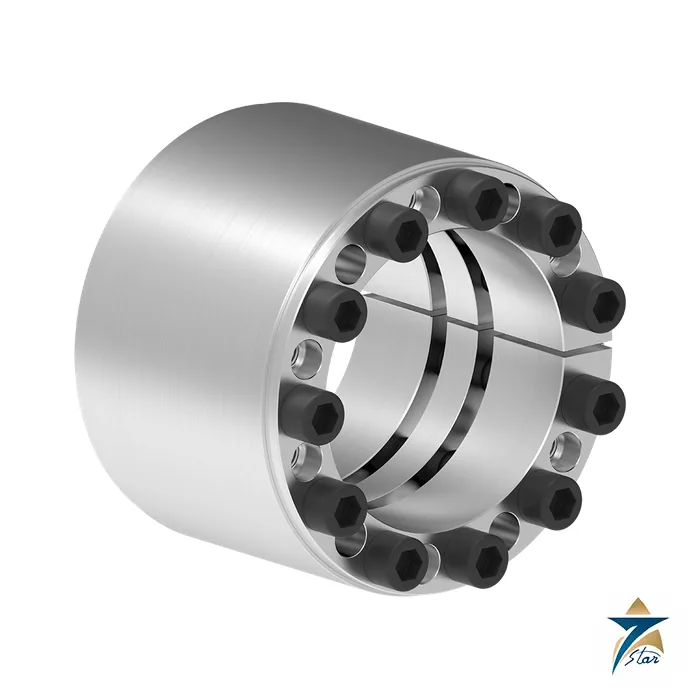
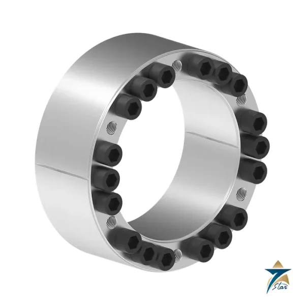
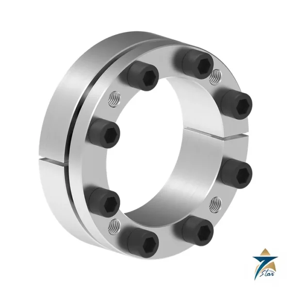
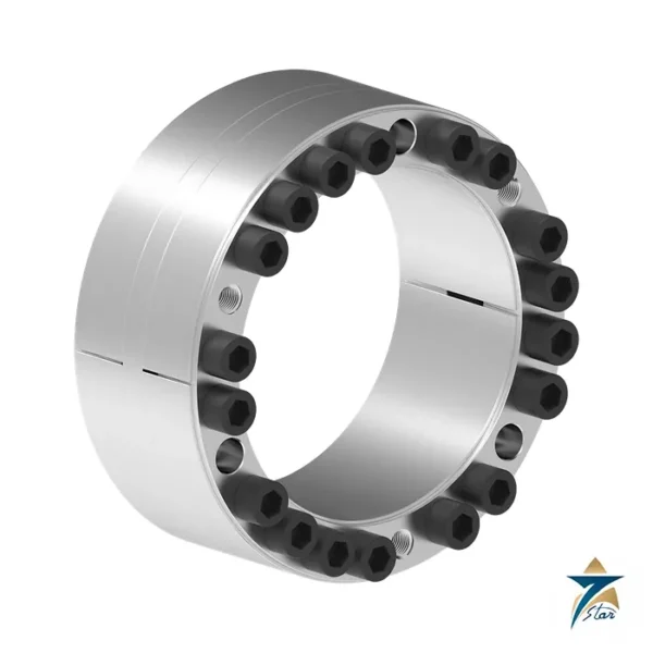
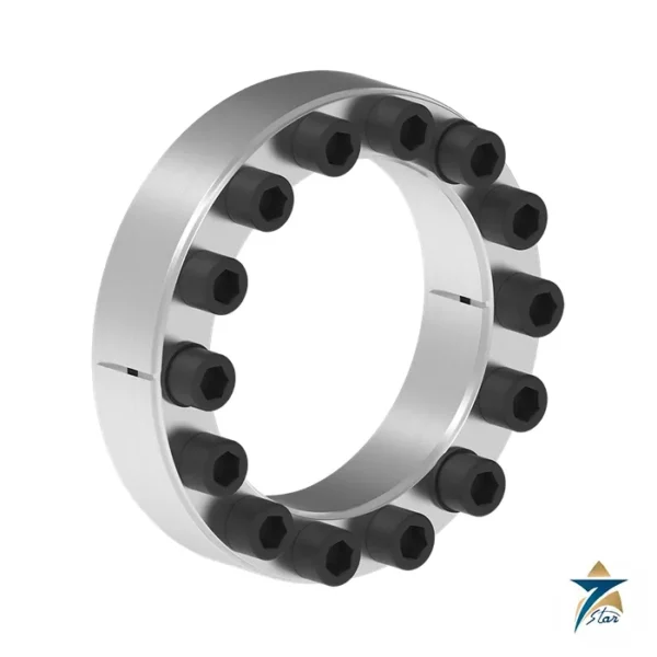
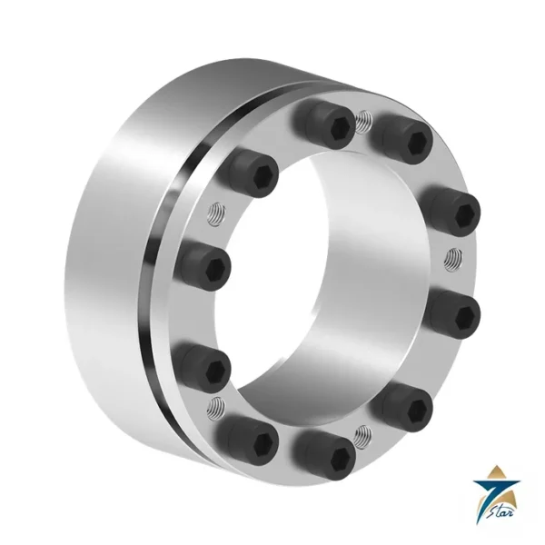
The RfN 7005 is a three-piece, slit, self-centring locking assembly designed for the highest torques in the RINGFEDER locking assembly programme. Its long, flat cone keeps axial displacement low, and the front and rear thrust rings are released separately through their own release threads. The tech paper lists shaft diameters from 25 to 600 mm and a torque range of 649 Nm to 1,760,000 Nm, so a single series covers everything from a small gearbox shaft to a large mill pinion or conveyor drum shaft.
RINGFEDER names two special features: low axial displacement, and the highest torque transfer of the self-centring family. Even so, the hub moves a little during mounting, and the tech paper describes this minor axial displacement as part of the design.
Technical specifications
| Parameter |
Specification |
| Manufacturer |
RINGFEDER POWER TRANSMISSION GmbH, Groß-Umstadt, Germany |
| Series |
RINGFEDER RfN 7005 locking assembly, three-piece, self-centring, slit |
| Shaft diameter d |
25 to 600 mm |
| Hub bore diameter D |
55 to 695 mm |
| Overall length L |
46 to 224 mm |
| Transmissible torque T |
649 Nm (25 x 55) to 1,760,000 Nm (600 x 695) |
| Transmissible axial force Fax |
64 kN to 5,860 kN |
| Surface pressure on shaft pW / hub pN |
155 to 250 N/mm2 / 75 to 125 N/mm2 |
| Locking screws |
M6 to M22; 6 to 33 screws depending on size |
| Screw tightening torque TA |
17 Nm to 930 Nm |
| Weight |
0.5 kg to 139 kg |
| Surface finish |
Shaft and hub bore Ra 1.6 um or better |
| Tolerances |
Shaft h8, hub H8 |
| Ordering example |
RfN 7005 35 60 (d = 35 mm, D = 60 mm) |
Selected sizes from the tech paper
The size table has 50 entries; weights are listed for each.
| d x D (mm) |
L (mm) |
T (Nm) |
Fax (kN) |
Screws |
TA (Nm) |
Weight (kg) |
| 25 x 55 |
46 |
649 |
64 |
6 x M6 |
17 |
0.5 |
| 45 x 75 |
62 |
3,050 |
135 |
7 x M8 |
41 |
1.1 |
| 75 x 115 |
90 |
11,700 |
313 |
10 x M10 |
83 |
3.3 |
| 100 x 145 |
114 |
25,725 |
514 |
11 x M12 |
145 |
6.1 |
| 200 x 260 |
165 |
140,000 |
1,400 |
16 x M16 |
360 |
22.4 |
| 300 x 375 |
197 |
428,000 |
2,850 |
20 x M20 |
690 |
49.7 |
| 460 x 555 |
224 |
980,000 |
4,260 |
24 x M22 |
930 |
109 |
| 600 x 695 |
224 |
1,760,000 |
5,860 |
33 x M22 |
930 |
139 |
Why choose three pieces
The extra ring buys two things. First, the flat cone angle multiplies the screw force into radial pressure, so torque per millimetre of shaft is high: the 100 x 145 size carries 25,725 Nm and 514 kN, and the 600 x 695 size carries 1,760,000 Nm and 5,860 kN with 33 screws of M22 tightened to 930 Nm. Second, separate release threads on each thrust ring make removal controlled rather than a fight with a seized cone.
Surface pressure on the shaft ranges from 155 to 250 N/mm2 and on the hub from 75 to 125 N/mm2, so the hub wall can usually be moderate, but the tech paper values are for ideal conditions and a hub check is still needed. Tolerances are shaft h8 and hub H8, finish Ra 1.6 um, and the ordering example is RfN 7005 35 60. For frequent assembly and disassembly or for heavy shock, add a safety margin above the nominal torque.
Confirm before ordering: torque and shock factor, hub material strength, and space for the release screws.
The product paper adds a caution for the design stage: arrangements with locking assemblies placed under or above bearings should be avoided where possible or investigated more closely, for example by test clamping, because the scatter of friction coefficients and the varying hub and hollow-shaft configurations make the exact stresses and deformations hard to predict.
Mounting the RfN 7005 step by step
Start with clean, dry contact faces. Remove protective coatings, paint and dirt from the shaft seat and hub bore, and check both against the h8 and H8 tolerances and the surface finish given in the tech paper. Lubricate the locking assembly as RINGFEDER instructs; do not use lubricants containing molybdenum disulphide or other additives unless the instructions call for them, because a change in friction alters the clamping force. Slide the assembly into the hub, position the hub on the shaft, and tighten the locking screws gradually in several passes around the circle, working diametrically opposite where the instructions say so, until every screw reaches the listed tightening torque with a calibrated torque wrench. A final check pass, with no screw still turning, confirms an even clamp.
Removal and re-use
To release, loosen the locking screws evenly, then use the release threads on the front and rear thrust rings as the tech paper describes, so each cone is pushed apart in a controlled way. Before refitting, clean the parts and inspect cones, screws and contact faces for scoring, fretting or corrosion. Replace screws that show damage, and follow RINGFEDER guidance on whether the assembly can be re-used for the duty involved.
Site conditions in Oman and the GCC
Shaft-hub connections on conveyors, crushers and mixers in the region often work in dusty, hot and sometimes humid air. Fit the assembly indoors or under cover where possible, and keep sand away from the cones and screws during assembly, since a few grains trapped on a contact face can change friction and leave a local high spot. On coastal sites and in desalination or port plant, salt air can start fretting corrosion at the joint edges, so protect exposed faces after mounting and consider a seal or cover arrangement in the machine design. Store spare assemblies in their original packaging in a dry room rather than in an open container yard, where heat and humidity cycles promote rust.
Checks during maintenance
At planned shutdowns, look for signs of slip such as witness marks, rust dust at the shaft-hub line or a hub that has shifted axially. Check screw torque at the intervals set by your maintenance plan and the RINGFEDER instructions, and never top up only a few screws, since uneven torque defeats the self-centring design. If the drive has seen an overload, jam or heavy shock, inspect the joint before restarting. Record the size, screw torque and date of each mounting so later teams can follow the same procedure.
Documents and quotation
The PDF is the RINGFEDER RfN 7005 tech paper (05.2024). Drive items to pair with it are listed under Electric Motors and Gear Units. Send shaft diameter, torque and hub material for a size proposal.



Reviews
There are no reviews yet.