A single valve for pressure and flow limits
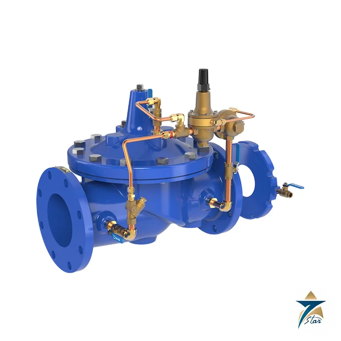
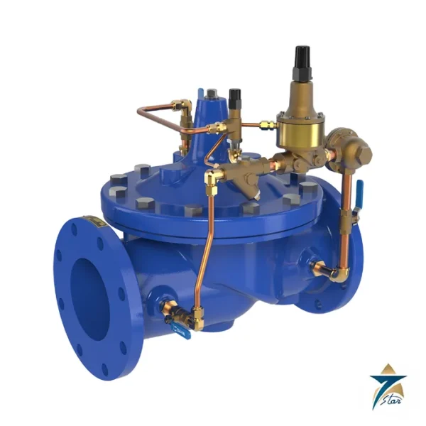
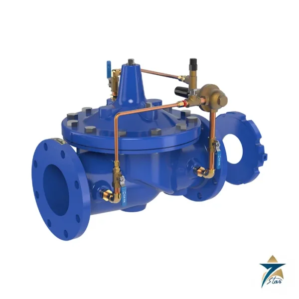
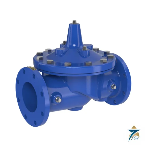
The Cla-Val 49-01 reduces a higher inlet pressure to a steady lower downstream pressure, as long as flow stays below a preset maximum, and it also limits flow to a preselected maximum rate. The 49-01 uses the full internal port Hytrol 100-01, and the 649-01 uses the reduced-port 100-20, so the same function can be had in a smaller or a larger capacity body.
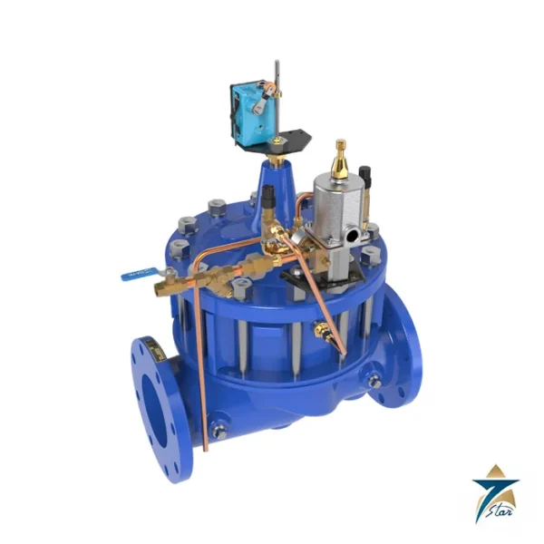
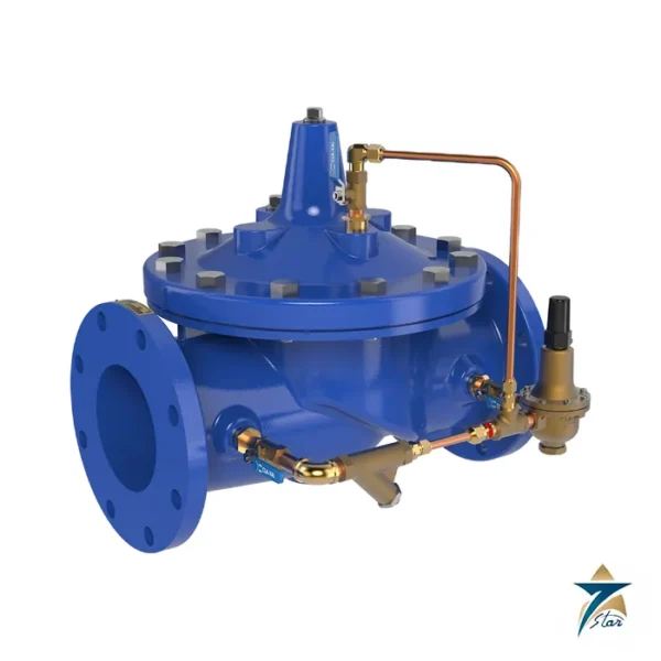
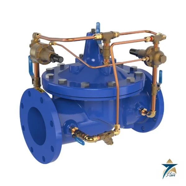
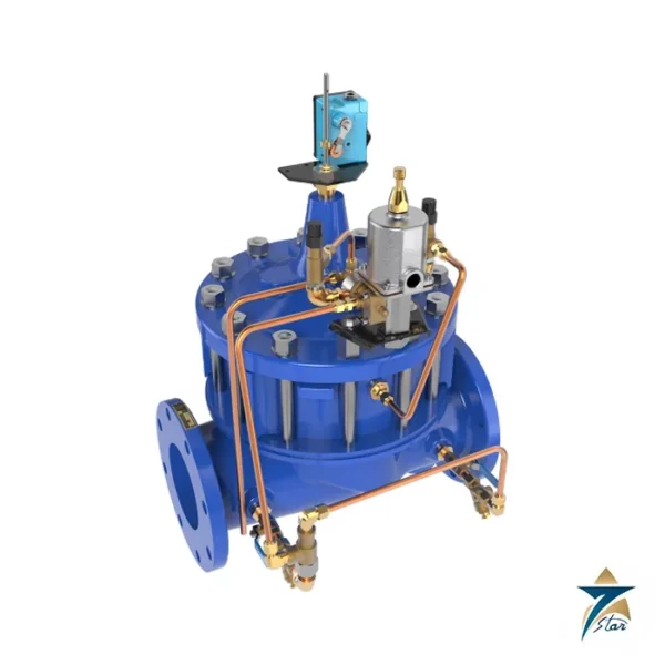
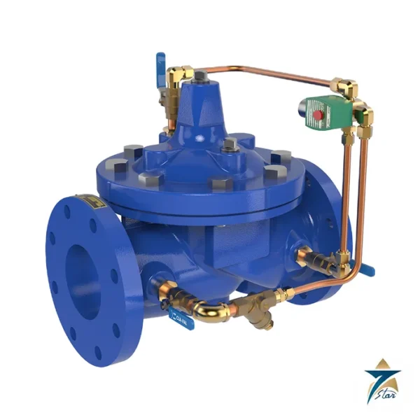
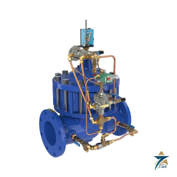
The valve is hydraulic and pilot controlled. A direct-acting CRA pressure reducing pilot responds to slight variations in downstream pressure, while a CDHS-18 differential control responds to the pressure drop across an X52E orifice plate in the main line. An optional check feature closes the valve on pressure reversal.
Technical specifications
| Parameter |
Specification |
| Model |
Cla-Val 49-01 (full port, 100-01 Hytrol) and 649-01 (reduced port, 100-20) |
| Sizes, 49-01 |
40 to 900 mm (1-1/2 to 36 in), globe or angle |
| Sizes, 649-01 |
3 to 48 in (80 to 1,200 mm), flanged, globe or angle by size |
| Body and cover |
Ductile iron A536, cast steel A216-WCB or bronze UNS 87850 |
| Pressure limits (psi) |
Iron 250/400, steel 285/400, bronze 225/400 for 150 class / 300 class flanges, grooved or threaded ends |
| Pilot system |
CRA pressure reducing pilot; CDHS-18 differential control; X52E orifice plate assembly |
| CRA adjustment ranges |
2-30, 15-75, 30-300 psi |
| Temperature |
Water to 180 °F |
| Suggested max. flow, 49-01 (gpm) |
125 (1-1/2 in), 300 (2-1/2 in), 1,800 (6 in), 4,900 (10 in), 11,000 (16 in) |
| Suggested max. flow, 649-01 (gpm) |
260 (3 in), 580 (4 in), 1,025 (6 in), 2,300 (8 in), 6,400 (12 in), 28,000 (30 in) |
| Options |
Flow clean strainer, isolation valves, speed controls, check valves, gauge, position indicator, Y-strainer |
Setting the two limits
The CRA pressure range is chosen at order from 2 to 30, 15 to 75 or 30 to 300 psi. The flow limit is set by the bore of the orifice plate and fine-tuned at the CDHS-18, with the low-flow level at one quarter of maximum flow. As with the 40-01, the plate sits one to five pipe diameters downstream with its sensing connection on the side of the assembly, and not directly on a butterfly valve.
Standard pilot materials are low-lead bronze with stainless steel 303 trim and orifice plate and Buna-N rubber, with aluminum, stainless steel or Monel optional. Water to 180 °F is the listed temperature range.
Choosing between the 49-01 and 649-01
For the full-port 49-01 the suggested maximum flow is 210 gpm at 2 in, 460 gpm at 3 in, 800 gpm at 4 in, 1,800 gpm at 6 in and 3,100 gpm at 8 in. The reduced-port 649-01 is offered flanged in 3 to 48 in (80 to 1,200 mm) with suggested maximum flows of 260 gpm at 3 in, 580 gpm at 4 in, 1,025 gpm at 6 in, 2,300 gpm at 8 in and 28,000 gpm at 30 in.
As general engineering background, a combined function like this suits a connection with a contracted maximum demand, where the network pressure is regulated and the consumption is capped by the same valve.
How the Cla-Val 49-01 works
The 49-01 is a diaphragm main valve that is moved by line pressure through a pilot system. The pressure reducing pilot watches the downstream pressure. If this pressure goes above the setting, the pilot closes the main valve a little, and if it falls below, the pilot opens it. The differential control watches the pressure drop across the orifice plate, which shows the flow. When the flow reaches the preset limit, it closes the main valve to hold the flow at that limit. The lower of the two demands controls the valve.
Where the 49-01 is used
- Water distribution mains and zone feeds
- Pump stations that must limit demand
- Industrial plants with a shared water supply
- Fire protection and booster systems
- Branch lines that need a steady pressure and a flow cap
Selection checklist for the 49-01
- Line size from 40 to 900 mm for the 49-01
- Full port 49-01 or reduced port 649-01
- Body material: ductile iron, cast steel or bronze
- Flange class, grooved or threaded ends
- Pressure reducing pilot range: 2-30, 15-75 or 30-300 psi
- Maximum flow for the orifice plate
- Options such as a strainer, a check feature or a position indicator
- Water temperature, up to 180 degrees F
Installation, commissioning and maintenance notes
Install the valve with isolation valves and a strainer on the inlet to protect the pilots. Put the orifice plate one to five pipe diameters downstream, with the sensing connection in the correct position. Bleed air from the cover and the pilots. Adjust the pressure setting first, then the flow limit at the differential control. Watch the valve during a flow change to confirm that it moves smoothly. Keep the pilot tubing and the strainer clean.
Requesting a quotation for the Cla-Val 49-01
Please send the line size, the end connections, the pressure range, the maximum flow and the body material. Seven Star LLC serves industrial customers in Oman and the GCC and replies with a quotation based on the information provided.
49-01 pilot system
The pilot system has a CRA pressure reducing pilot, a CDHS-18 differential control and an X52E orifice plate.
49-01 pressure limits
The limits are 250 psi for iron, 285 psi for steel and 225 psi for bronze in the 150 class, with 400 psi in the 300 class.
49-01 flow guide
The suggested maximum flow is 300 gpm in 2-1/2 inch, 1,800 gpm in 6 inch and 4,900 gpm in 10 inch sizes.
49-01 check feature
An optional check feature closes the valve if the pressure reverses.
Control valve records for 49-01
Keep the pilot settings, the orifice plate size and the service dates with the valve file.
Documents and quotation
The engineering data sheet E-49-01/649-01 is attached, with inch and metric dimensions. Confirm the size, pressure class, pressure and flow set points, orifice bore and options before ordering. Related valves under Control Valves include the Cla-Val 90-01 pressure reducing valve and the 40-01 rate of flow valve.








Reviews
There are no reviews yet.