- Automation & ControlView all 1,851 products
- AC Drives
- PLC & I/O Cards
- Industrial Communications
- Vibration Monitoring
- Automation Accessories
- Controllers & Data Acquisition
- Isolator & Barrier
- CCTV & Security
- Safety Switches & Guard Locking
- Encoders
- HMI Displays
- Industrial Computers
- Servo Drives
- Motor Soft Starters
- Pneumatic Cylinders
- Machine Vision
- Automation Software
- Robotics
















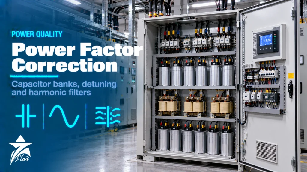
Industrial plants draw reactive power for motors, transformers and welding equipment, and increasingly they also inject harmonic currents from variable speed drives, rectifiers and UPS systems. Left uncorrected, low power factor raises current in cables and transformers, wastes capacity and can attract utility penalties, while harmonics overheat equipment and cause nuisance trips. Power factor correction with capacitor banks and the right harmonic mitigation solves both problems, but only if the two are designed together. A plain capacitor bank installed in a network full of drives can create resonance and fail within months. This guide explains how to size correction, when to use detuned banks or filters, and what to check in hot GCC substations.
Power Factor Basics
Power factor is the ratio of active power (kW) to apparent power (kVA). Induction motors and transformers need magnetising current, which shows up as reactive power (kvar) and lowers displacement power factor. A 4-pole motor at full load might run at 0.85, but at half load it can drop well below 0.75.
When harmonics are present, a further distinction matters. Displacement power factor considers only the fundamental frequency, while true power factor also includes the effect of harmonic currents. Capacitors improve displacement power factor; they do nothing for the distortion component and can make it worse. That is why plants with many drives sometimes add capacitors and see little improvement in true power factor.
- Lower current for the same kW, freeing capacity in transformers, cables and switchgear.
- Reduced I²R losses in cables and transformers.
- Better voltage regulation at the end of long feeders.
- Avoidance of reactive energy charges or penalties where the utility tariff includes them; check the applicable tariff for the site.
Sizing the Capacitor Bank
The reactive power required to raise power factor from an existing value to a target value is found from the active load:
Qc = P × (tan φ1 − tan φ2), where P is the active power in kW, φ1 is the angle at the existing power factor and φ2 is the angle at the target power factor.
For example, a 500 kW load at 0.78 has tan φ1 of about 0.80; the target of 0.95 gives tan φ2 of about 0.33. The required correction is roughly 500 × 0.47, or about 235 kvar. In practice, designers check the load profile over a full operating cycle with a power quality analyser, because the minimum and maximum reactive demand decide how many steps the bank needs and whether it can over-correct at light load.
| Correction type | Where used | Advantages | Limitations |
|---|---|---|---|
| Individual (at the motor) | Large constant-speed motors running long hours | Reduces current in the motor feeder; switched with the motor | Not for motors on VFDs or soft starters; risk of self-excitation if oversized |
| Group | Motor control centres or sub-distribution boards | Lower cost per kvar than individual correction | Feeders upstream of the bank still carry reactive current |
| Central automatic bank | Main LV switchboard | Follows load changes with stepped switching; easy to maintain | Internal plant cables still carry reactive current |
| Fixed bank | Transformer no-load compensation, constant loads | Simple and low cost | Can over-correct at light load |
| Thyristor-switched or active compensation | Fast-changing loads such as welders and cranes | Very fast response without switching transients | Higher cost and heat dissipation |
Individual capacitors must never be connected on the output of a VFD; drives with a DC bus already present a high displacement power factor to the supply, and capacitors at their output can damage both drive and capacitor.
Harmonics: Where They Come From
Non-linear loads draw current in pulses rather than smooth sine waves. A six-pulse drive rectifier produces characteristic harmonics at the 5th, 7th, 11th and 13th orders, with the 5th usually the largest. UPS rectifiers, DC drives, LED lighting, IT loads and arc furnaces add their own spectra. Harmonic currents flowing through the network impedance distort the voltage seen by all other equipment.
- Transformer and cable overheating, especially in neutral conductors where triplen harmonics add.
- Capacitor overload and premature failure.
- Nuisance tripping of breakers and malfunction of sensitive electronics.
- Motor heating and torque pulsations.
- Interference with metering and communication circuits.
The VFD selection guide for hot climates covers drive-side options such as DC chokes, line reactors and multi-pulse front ends, which reduce harmonics at the source.
Resonance: Why Plain Capacitors Can Fail
Capacitors and the inductance of the supply transformer form a parallel resonant circuit. The approximate resonant harmonic order is:
h ≈ √(Ssc / Qc), where Ssc is the short-circuit power at the bank’s busbar in kVA and Qc is the connected capacitor rating in kvar.
Take a 1600 kVA transformer with 6% impedance, giving a short-circuit level of roughly 26,700 kVA at the LV busbar. With 400 kvar of capacitors in service, h is about 8.2; with 600 kvar it falls to about 6.7, moving towards the 7th harmonic. As an automatic bank switches steps in and out, the resonance point sweeps across the characteristic harmonics. If it coincides with a harmonic that drives produce, voltage distortion and capacitor current rise sharply, leading to blown fuses, bulging cans and failures.
Detuned Capacitor Banks
A detuned bank places a reactor in series with each capacitor step, tuning the combination below the lowest significant harmonic. Above the tuning frequency the step appears inductive, so it cannot resonate with the supply at the 5th or higher harmonics.
| Detuning factor p | Tuning frequency at 50 Hz | Typical use |
|---|---|---|
| 5.67% | about 210 Hz (order 4.2) | Networks with moderate 5th harmonic; absorbs more harmonic current |
| 7% | about 189 Hz (order 3.8) | The most common choice for plants with six-pulse drives |
| 14% | about 134 Hz (order 2.7) | Networks with significant 3rd harmonic or ripple control signals |
The tuning frequency follows from f ≈ 50 / √p. Because the reactor raises the voltage across the capacitor, detuned banks use capacitors with a higher rated voltage than the network, and the effective kvar output must be calculated for the combination, not taken from the capacitor rating alone. Detuned banks are not filters: they protect the capacitors and avoid amplifying harmonics, but they remove only a modest share of the existing distortion.
Harmonic Filters: Passive and Active
Passive tuned filters
A passive filter is tuned close to a specific harmonic, often just below the 5th, to absorb a large share of that current. It also supplies reactive power at the fundamental. Passive filters are cost-effective for large, stable loads, but they must be designed with the network’s other harmonic sources in mind, because they can absorb harmonics from outside the plant and become overloaded.
Active harmonic filters
An active filter measures load current and injects a compensating current to cancel harmonics across a wide range of orders, typically up to the 50th. It adapts to changing load and cannot resonate with the network. Many active filters can also correct displacement power factor and balance phase loads. Their limitations are higher cost per ampere, heat losses that must be removed from the switchroom, and dependence on electronics that need cooling.
Standards and Limits
- IEEE 519-2022: recommends voltage distortion limits at the point of common coupling and current distortion limits that depend on the ratio of short-circuit current to load current; often referenced in specifications in the GCC.
- IEC 61000-3-x and 61000-2-4: emission limits and compatibility levels for equipment and industrial networks.
- IEC 60831-1 and -2: self-healing shunt power capacitors for AC systems up to 1000 V.
- IEC 61921: LV power factor correction banks.
- IEC 60947-4-1 utilization category AC-6b: applies to contactors switching capacitor banks.
- Local utility or regulator grid codes, which may set power factor targets and harmonic limits at the connection point.
Switching, Protection and Heat in GCC Substations
Capacitor steps should be switched with contactors designed for capacitor duty, which typically include pre-charge resistors or early-make contacts to limit inrush current, or with thyristor modules for fast switching. Each step needs short-circuit protection by fuses or circuit breakers rated for the capacitive current, which is normally taken as 1.3 to 1.5 times the nominal current to allow for harmonics and voltage tolerance.
Capacitor life is closely linked to temperature. Capacitors have temperature categories, and continuous operation in hot switchrooms shortens their life. Panels need forced ventilation or air conditioning sized for the losses of reactors and capacitors, which are significant in detuned banks. Measure capacitance periodically: a step that has lost a significant share of its rated capacitance should be replaced, and a bulging case is a sign of internal failure.
Capacitors on generator supply
Plants that transfer to standby diesel generators need a clear rule for the capacitor bank. A generator carrying a light load with capacitors connected can be pushed into leading power factor, where the alternator’s voltage regulator loses control and the voltage rises. Most designs therefore block or reduce capacitor steps when the generator is supplying the plant, using a signal from the transfer switch to the power factor controller. Harmonic distortion is also higher on generator supply, because the generator’s impedance is much higher than that of a utility transformer, so filters and drives should be checked for generator operation as well.
Power Quality Survey Before You Buy
A survey of at least one full operating cycle, often a week, at the main incomer and major feeders provides the information that sizing needs: kW, kvar and power factor profiles, voltage and current harmonic spectra, total harmonic distortion, and unbalance. It also captures existing resonance problems. Without it, a capacitor bank is a guess.
Power Factor Correction Checklist
- Load profile with minimum and maximum reactive demand.
- Harmonic spectrum and distortion levels at the connection point.
- Transformer rating and impedance to estimate resonance.
- Utility power factor target and harmonic limits.
- Choice of plain, detuned, filter or active solution justified by the survey.
- Capacitor voltage rating and detuning factor confirmed.
- Capacitor-duty contactors or thyristor switches, and protection sized for capacitor current.
- Panel ventilation and switchroom temperature checked.
Power Factor Correction Products We Supply
These products cover the controller, capacitors and switching.
| Product | Type | Where it fits |
|---|---|---|
| Lovato DCRL8 8-Step Automatic Power Factor Controller | Automatic power factor controller | Switching capacitor steps to hold the target power factor. |
| Circutor computer SMART III 14 Power Factor Controller | Power factor controller | Capacitor banks with up to 14 steps. |
| TDK B32305A4252B040 DeltaCap X Black 25 kvar 440 V Capacitor | Power capacitor | Capacitor bank steps. |
| TDK B44066S2410J230 Capacitor Contactor 22 kvar, 230 V Coil | Capacitor contactor | Switching capacitor steps and limiting inrush current. |
| Datakom DFC-0124 Reactive Power Controller | Reactive power controller | Capacitor bank control. |
Send the transformer rating, load profile and any harmonic measurements through our quote request form.
Sourcing Power Factor Correction Equipment Through Seven Star LLC
Seven Star LLC supplies capacitors, detuning reactors, power factor controllers, power modules and other electrical components on request for industrial plants in Oman and the GCC. We help with selection and cross-checking part numbers when replacing steps in existing banks. Availability and lead time are confirmed at quotation.
Send us the nameplate data of your existing capacitor bank, reactors and controller, or your survey results and RFQ, and we will return a checked, itemised quotation.
Frequently asked questions
What power factor should an industrial plant target?
Many plants aim for 0.95 or higher at the point of supply, but the target depends on the local utility tariff and grid code. Correcting above about 0.98 rarely adds benefit and increases the risk of over-correction at light load.
How do I calculate the kvar needed for power factor correction?
Use Qc = P × (tan φ1 − tan φ2), where P is the active load in kW and φ1 and φ2 are the angles of the existing and target power factor. A load profile over a full operating cycle shows the minimum and maximum reactive demand and the number of steps needed.
What is a detuned capacitor bank?
A detuned bank has a reactor in series with each capacitor step, tuning the combination below the lowest major harmonic, commonly at 189 Hz with a 7% reactor on a 50 Hz network. This prevents the bank from resonating with the supply and protects the capacitors from harmonic overload.
Why do capacitor banks fail in plants with VFDs?
Capacitors combined with the transformer inductance form a resonant circuit. If its resonant frequency is near a harmonic produced by drives, typically the 5th or 7th, harmonic voltage and current are amplified, which overheats and damages capacitors. Detuned banks or filters avoid this.
What is the difference between active and passive harmonic filters?
A passive filter is a tuned reactor and capacitor circuit that absorbs mainly one harmonic and supplies reactive power. An active filter uses power electronics to inject cancelling current across many harmonic orders and adapts to load changes, at a higher cost per ampere.
Which contactors are used for capacitor switching?
Contactors rated for capacitor switching, utilization category AC-6b under IEC 60947-4-1, are used. They often include pre-charge resistors or early-make contacts to limit the high inrush current when a step is energised. Thyristor switches are used where very fast switching is needed.
Was this guide helpful?One click helps us write better guides for engineers.
Thank you! Glad it helped. Need this equipment for your project? Request a quotation
Thank you. We will use this to improve the guide.