Eight analog outputs in a single ControlLogix slot
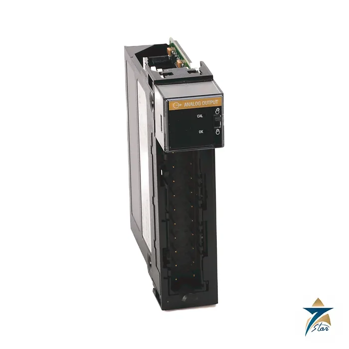
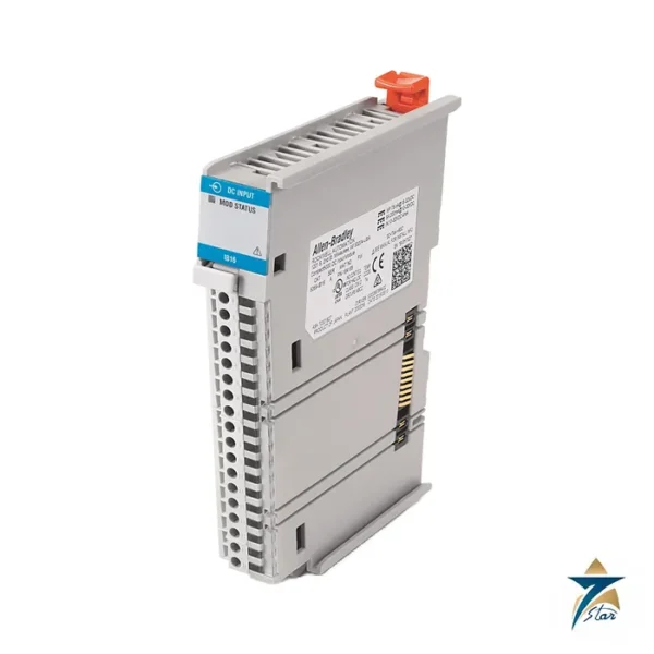
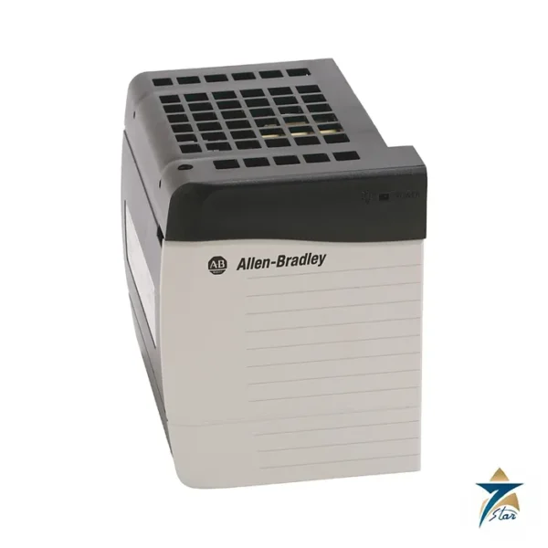
The Allen-Bradley 1756-OF8 is a ControlLogix analog output module with eight channels. Each channel can be set to a voltage output of ±10V or a current output of 0 to 20 mA, so one module can drive valve positioners, drives, chart recorders and other analog loads. It occupies one chassis slot.
Resolution is 15 bits across 10.5V in voltage mode (320 µV per bit) and 16 bits across 21 mA in current mode (325 nA per bit). Settling time is under 2 ms to 95% of the final value with resistive loads, and calibrated accuracy at 25 °C is better than 0.05% of range.
Technical specifications
| Parameter |
Specification |
| Catalog number |
1756-OF8 (1756-OF8K conformal coated) |
| Module type |
ControlLogix 8-channel voltage/current analog output module |
| Outputs |
Eight voltage or current outputs, not isolated from each other |
| Output ranges |
±10V and 0…20 mA |
| Resolution |
Voltage: 15 bits across 10.5V, 320 µV/bit; current: 16 bits across 21 mA, 325 nA/bit |
| Signal range and counts |
0…21.2916 mA and -10.4336…+10.4336V, -32,768 to 32,767 counts |
| Drive capability |
Voltage: more than 2000 Ω; current: 0…750 Ω |
| Settling time |
Less than 2 ms to 95% of final value with resistive loads |
| Calibrated accuracy at 25 °C |
Better than 0.05% of range |
| Module error |
Voltage 0.1% of range; current 0.2% of range |
| Module scan time, min |
12 ms floating point; 8 ms integer |
| Data format |
Integer (left justified, 2s complement) or IEEE 32-bit floating point |
| Backplane current |
200 mA at 5.1V DC and 300 mA at 24V DC; 8.22 W total backplane power |
| Thermal dissipation |
28.03 BTU/hr |
| Overvoltage protection |
±24V DC |
| Short-circuit protection |
Electronically current limited to 21 mA or less |
| Isolation |
250V continuous, outputs to backplane; no isolation between channels |
| Terminal block |
1756-TBNH (screw) or 1756-TBSH (spring), 20-pin |
| Operating temperature |
Chassis series C: 0…+60 °C; chassis series B: 0…+55 °C |
| Temperature code (as printed) |
T4 |
| Certifications (as printed) |
cULus, FM Class I Division 2, CE, RCM, ATEX and IECEx (II 3 G Ex ec IIC T4 Gc), KC, UKEx, UKCA, CCC |
Drive limits and protection
In voltage mode the module can drive loads above 2000 ohms; in current mode the load can be 0 to 750 ohms. Outputs are protected to ±24V DC and are electronically limited to 21 mA or less on a short circuit. For current outputs the module can detect an open circuit when the output is set above 0.1 mA. The channels share a return and have no isolation from each other, though the whole output side is isolated to 250V continuous from the backplane.
The backplane load is 200 mA at 5.1V and 300 mA at 24V, which comes to 8.22 W. Keep this in mind when calculating the chassis power budget.
Wiring and variants
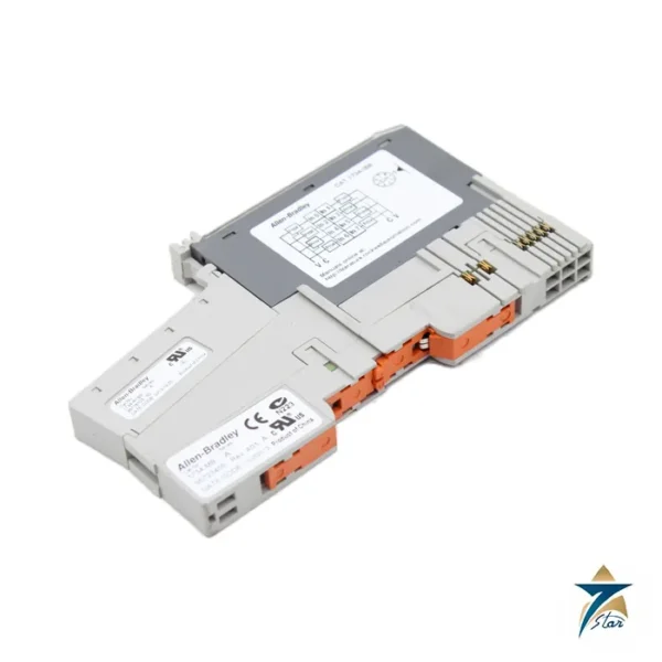
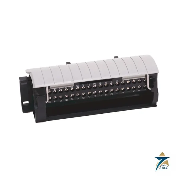
The module uses a 20-pin removable terminal block, the 1756-TBNH screw type with a 1.36 N•m torque or the 1756-TBSH spring type, ordered separately. The standard housing is not deep enough for 2.5 mm² (14 AWG) wire, so use the extended 1756-TBE housing in that case. The 1756-OF8K is the conformal-coated version, and the 1756-OF8H adds HART communication.
Planning the eight channels
Because the eight outputs share a common return and are not isolated from one another, the first design question is whether every connected device can sit on that shared reference. Positioners and recorders in the same control room usually can, but a receiver powered from a different supply or located in a remote building may introduce ground loops or offsets. Where a field device needs galvanic separation, plan a signal isolator in the loop or move that signal to a separate module, and record the decision on the I/O allocation sheet.
For each current loop, add the receiver input resistance to the round-trip cable resistance and keep the total within 0 to 750 ohms; for each voltage output, confirm the receiver impedance is above 2000 ohms. Then add the 200 mA at 5.1 V and 300 mA at 24 V to the chassis power supply calculation alongside the other modules in the same chassis, and check the chassis series against the operating temperature limits in the table.
Mounting and terminal block wiring
Insert the module into a free slot, wire the chosen 20-pin terminal block before fitting it, and keep the removable terminal block keyed to this module so it cannot be fitted to the wrong slot during maintenance. Use the extended housing mentioned above whenever 14 AWG conductors are needed. Run analog output pairs in shielded cable, separated from motor and lighting circuits inside the cabinet and on cable trays.
Configuration and loop checks
In the controller project, select voltage or current mode for each channel, choose integer or floating-point data and set scaling in engineering units. Configure the output behaviour for program mode and communication loss so that each actuator goes to a defined safe state. Enable open-wire detection on current channels where the field device would otherwise fail silently. During loop checks, step each output through several values, read the result at the device end and verify that valve or damper travel matches the command.
Cabinet conditions at Gulf sites
A ControlLogix chassis with several I/O modules releases a significant amount of heat, and this module alone contributes the backplane power shown above. Summer heat in Oman can push cabinet temperatures toward the chassis limits, especially in outdoor kiosks or poorly ventilated switch rooms, so confirm cooling capacity with all modules installed. Desert dust settles on module vents and terminal blocks, and coastal sites add humidity and salt; sealed enclosures with filtered or air-conditioned cooling and regular filter changes help protect the electronics. The conformal-coated version named above is the variant listed for harsher atmospheres, so compare it with the standard module when specifying.
Upkeep during shutdowns
During planned outages, check terminal screw tightness, inspect cable entries and shields, clean dust from the chassis area and compare commanded values with field readings on key control loops. Keep a spare module and terminal block for critical processes.
Documents and quotation
The Rockwell Automation ControlLogix analog I/O installation instructions are attached; the complete technical data is in publication 1756-TD002 on the Rockwell Automation literature library. See our PLC and I/O cards catalogue for chassis and controllers. Confirm the exact catalog number, series letter and firmware or hardware revision on the product label, and the compatibility with your existing system, before ordering. Stock and lead time are confirmed at quotation.




Reviews
There are no reviews yet.