Two-piece self-centring locking assembly for true-running parts
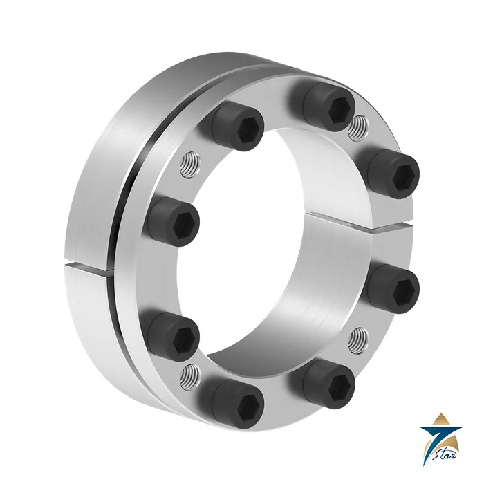
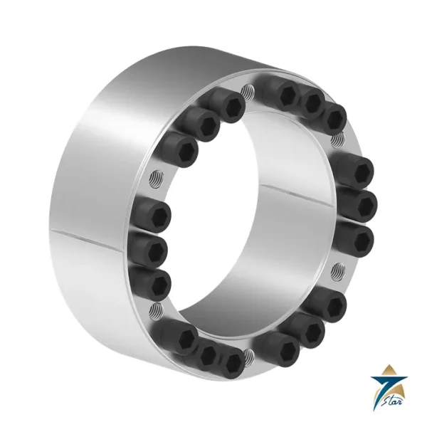
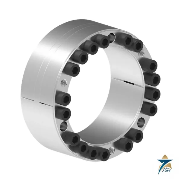
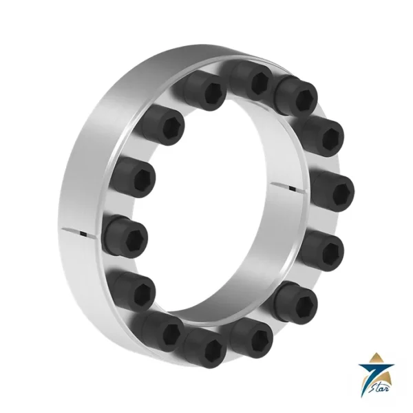
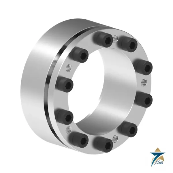
The RfN 7003 is a two-piece, slit, single-taper locking assembly without a flange, made for shafts from 19 to 400 mm. Because it is slit, it tolerates wider shaft and hub tolerances than an unslit ring, and RINGFEDER lists it as self-centring, so the hub runs true on the shaft. During tightening the hub shifts slightly toward the screw head. Disassembly needs only a few release screws, and the stiffer geometry of the flange region deforms far less than on standard products.
The tech paper lists three strengths: excellent concentricity combined with easy dismantling, suitability for higher rotation speeds because the rings stay true to form during assembly, and suitability for high radial loads thanks to the material strength of the rings. That combination makes it a natural choice for gear wheels, pulleys and rotors on pumps and fans.
Technical specifications
| Parameter |
Specification |
| Manufacturer |
RINGFEDER POWER TRANSMISSION GmbH, Groß-Umstadt, Germany |
| Series |
RINGFEDER RfN 7003 locking assembly, self-centring, two-piece, slit, single taper, without flange |
| Shaft diameter d |
19 to 400 mm |
| Hub bore diameter D |
47 to 495 mm |
| Overall length L |
34 to 137 mm |
| Transmissible torque T |
355 Nm (19 x 47) to 512,635 Nm (400 x 495) |
| Transmissible axial force Fax |
31 kN to 2,326 kN |
| Surface pressure on shaft pW / hub pN |
130 to 305 N/mm2 / 120 to 190 N/mm2 |
| Locking screws |
M6 to M22; 5 to 21 screws depending on size |
| Screw tightening torque TA |
14 Nm to 780 Nm |
| Surface finish |
Shaft and hub bore Ra 1.6 um or better |
| Tolerances |
Shaft h8, hub H8 |
| Ordering example |
RfN 7003 24 50 (d = 24 mm, D = 50 mm) |
Selected sizes from the tech paper
The table runs to 45 sizes. The tech paper does not list weights for this series.
| d x D (mm) |
L (mm) |
T (Nm) |
Fax (kN) |
Screws |
TA (Nm) |
| 19 x 47 |
34 |
355 |
31 |
5 x M6 |
14 |
| 32 x 60 |
34 |
950 |
50 |
8 x M6 |
14 |
| 50 x 80 |
41 |
2,430 |
85 |
7 x M8 |
35 |
| 75 x 115 |
50 |
6,680 |
160 |
8 x M10 |
70 |
| 100 x 145 |
56 |
13,380 |
240 |
8 x M12 |
125 |
| 150 x 200 |
68 |
32,950 |
400 |
10 x M14 |
190 |
| 200 x 260 |
78 |
67,430 |
607 |
15 x M14 |
190 |
| 300 x 375 |
102 |
203,362 |
1,230 |
18 x M18 |
400 |
| 400 x 495 |
137 |
512,635 |
2,326 |
21 x M22 |
780 |
Choosing between the RfN 7003 and its relatives
The RfN 7003 is the base of a small family. The RfN 7004 is its extended version, where low pressure lets the hub be made smaller and cheaper. The RfN 7006 adds a larger flange diameter so the hub does not move axially during mounting, which matters with belt pulleys. The RfN 7003 itself accepts the small axial hub movement and in return needs no collar. At 75 x 115 it transmits 6,680 Nm and 160 kN with 8 M10 screws tightened to 70 Nm; at 400 x 495 the values are 512,635 Nm and 2,326 kN with 21 M22 screws at 780 Nm.
Shaft h8 and hub H8 apply, with Ra 1.6 um on both bores; the ordering example in the tech paper reads RfN 7003 24 50. Confirm before ordering: the axial position of the hub after tightening, hub strength, and whether shock torque requires a safety margin.
RINGFEDER lists further general benefits of keyless locking assemblies: inexpensive manufacture, because large tolerances and simple turning are enough; simple installation, because only a few screws are tightened and any angular position between hub and shaft is possible; and simple dismantling through threaded extraction holes. The connection is backlash-free, so there is no danger of deflection, and it needs no maintenance.
Working out the right size for the shaft and hub
Selection starts with the shaft diameter, which fixes the row in the RINGFEDER table, but it should not stop there. Compare the transmissible torque and axial force for that size with the peak loads of the drive, including starting torque, reversing loads and any shock that the driven machine can produce. Where the application combines torque and axial force, as on helical gears, check the combined load according to the method in the tech paper rather than reading each value on its own.
- Check the hub: its outside diameter and material must withstand the surface pressure on the hub bore. A thin-walled gear or pulley hub may need a stronger design or a different locking assembly.
- Confirm that the small axial shift of the hub toward the screw head during tightening is acceptable. If the hub must stay in an exact axial position, look at the RfN 7006 described above.
- Make sure there is room to reach all the locking screws with a torque wrench after the part is installed, including on machines with guards or close bearing housings.
- Specify the shaft and bore finish and tolerances on the machining drawing so the parts arrive ready for assembly.
Installation sequence
Clean the shaft and hub bore thoroughly and check them for burrs or damage. Follow the RINGFEDER instructions on the condition of the contact surfaces and on any lubrication of screws and taper surfaces, because friction conditions directly affect the torque the joint can carry. Slide the locking assembly into the hub, place the hub on the shaft, and bring it to the required axial and angular position.
Tighten the screws evenly in several passes, working around the circle rather than fully tightening one screw at a time. Finish with the specified tightening torque for the size, using a calibrated torque wrench, and repeat the final pass until no screw turns further at the set torque. Check concentricity and axial run-out of the hub before the machine is returned to service, especially on fast-running fan or pump rotors.
Removal, inspection and reuse
To dismantle, loosen the locking screws and use the release threads as the manufacturer describes, so the rings separate without force on the shaft or the bearings. Inspect the rings, screws and contact surfaces for scoring, corrosion or deformation before any reuse; damaged screws should be replaced with ones of the correct grade. If the hub has slipped in service, investigate the cause, such as an under-tightened screw, contaminated surfaces or a load above the selected size, rather than simply reassembling.
Notes for Oman and GCC installations
Keyless shaft connections are popular on pumps, fans and conveyors across the region because they avoid keyway machining and allow quick repositioning. Exposed shaft ends in coastal plants, desalination facilities and port equipment are prone to corrosion, so protect the visible faces of the locking assembly and the screw heads with a suitable coating or cover. Fine dust and sand can get between the contact surfaces during assembly on site; assemble in a clean area or protect the parts until the joint is tightened. Large daily temperature swings in outdoor machinery are a further reason to recheck screw torque at the first planned maintenance stop after installation.
Documents and quotation
The attached PDF is the RINGFEDER tech paper for the RfN 7003 (05.2024). Related gear units and motors are listed under Electric Motors and Gear Units. For a quotation, send the shaft and hub dimensions, torque, speed and application.


Reviews
There are no reviews yet.