Limiting flow to a preset maximum, whatever the line pressure
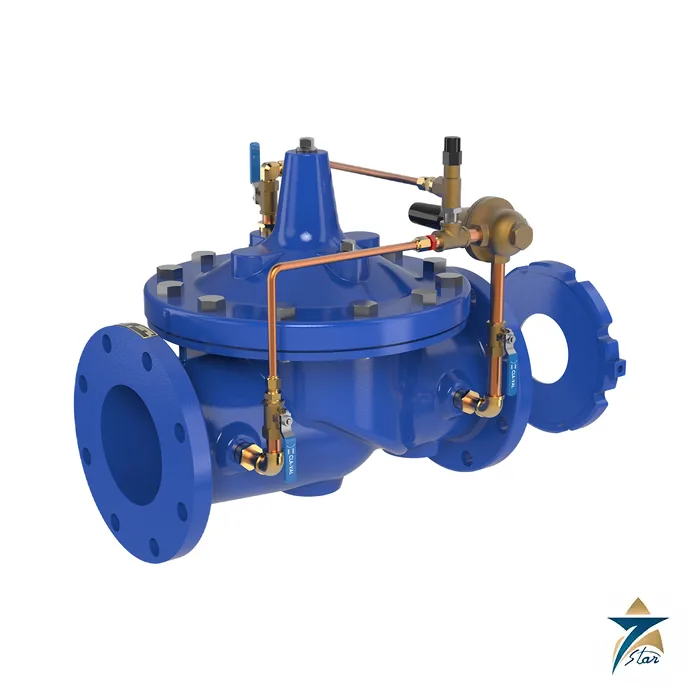
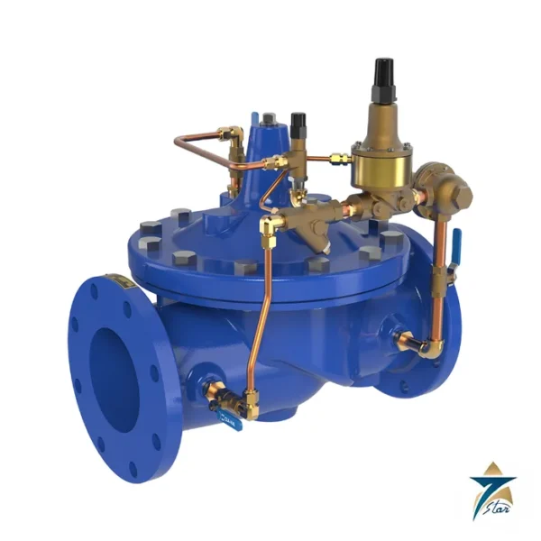
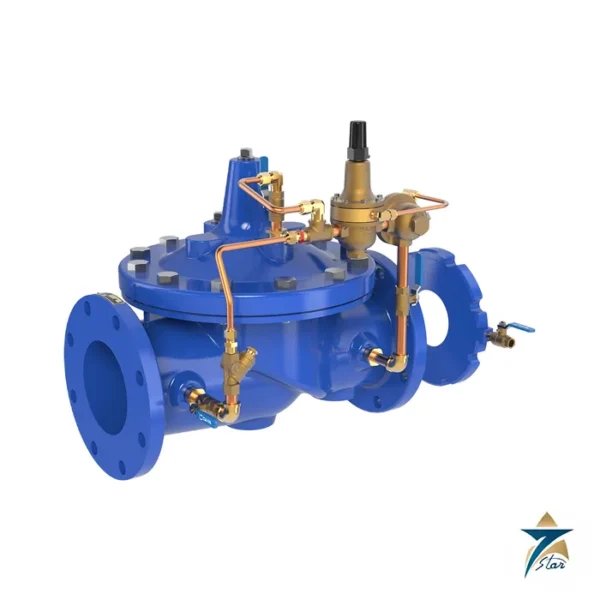
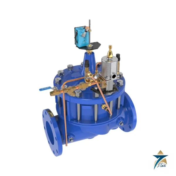
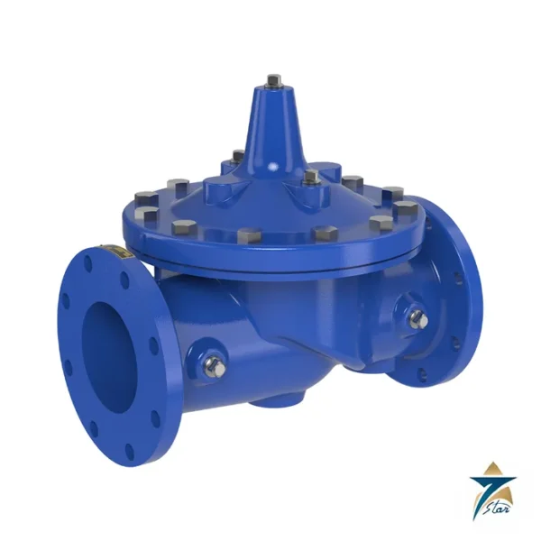
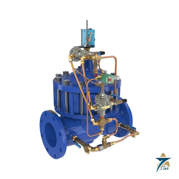
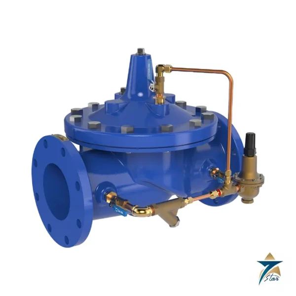
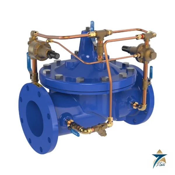
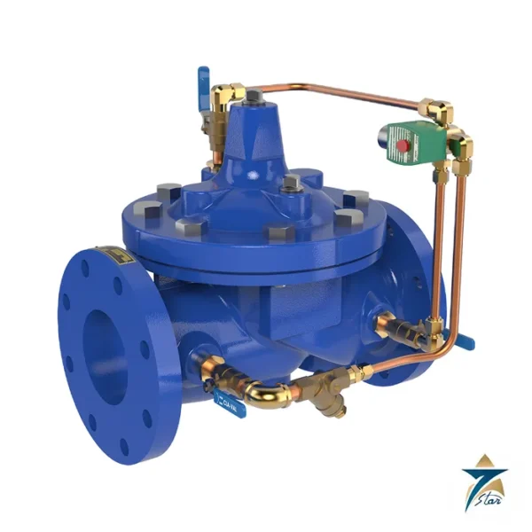
The Cla-Val 40-01 prevents excessive flow by limiting it to a preselected maximum rate regardless of changing line pressure. It is a hydraulically operated, pilot-controlled diaphragm valve on a Hytrol 100-01 body. A CDHS18 differential control reads the pressure drop across an orifice plate installed downstream, and very small changes in that differential make the main valve correct the flow immediately.
The flow rate is changed by turning an adjusting screw on the pilot control. Each valve comes with an X52E orifice plate assembly and holder, and an optional check feature closes the valve if pressure reverses.
Technical specifications
| Parameter |
Specification |
| Model |
Cla-Val 40-01 rate of flow control valve (uses 100-01 Hytrol) |
| Sizes |
1-1/2 to 36 in (40 to 900 mm), globe or angle; threaded, flanged or grooved by size |
| Body and cover materials |
Ductile iron ASTM A536, cast steel ASTM A216-WCB, bronze UNS 87850 |
| Max. pressure, 150 class / 300 class |
Ductile iron 250 / 400 psi; cast steel 285 / 400 psi; bronze 225 / 400 psi (grooved and threaded ends 400 psi) |
| Pilot system |
CDHS18 differential control; X58C restricting fitting; X52E orifice plate assembly |
| Temperature |
Water to 180 °F |
| Suggested max. flow (gpm, continuous) |
210 (2 in), 460 (3 in), 800 (4 in), 1,800 (6 in), 3,100 (8 in), 7,000 (12 in), 17,000 (20 in), 50,000 (36 in) |
| Suggested min. flow (gpm) |
1 (1-1/2 and 2 in), 2 (2-1/2 and 3 in), 4 (4 in), 10 (6 in), 15 (8 in), 35 (10 in) |
| Orifice plate and pilot trim |
Stainless steel 303 |
| Options |
X46A strainer, CK2 isolation valves, closing and opening speed controls, check valves, X141 gauge, X101 position indicator, X43 Y-strainer |
Installing the orifice plate and setting the flow
The datasheet says the orifice plate should be installed one to five pipe diameters downstream of the valve, with the sensing connection on the side of the orifice plate assembly in the pipeline. It may be attached to the main valve outlet flange, but better control is obtained downstream, and the assembly should not be mounted directly to a butterfly valve. Orifice bore selection follows the X52E data sheet; the low-flow setting equals one quarter of the maximum flow for the chosen bore.
The standard orifice plate is stainless steel 303, as is the pilot trim, with a low-lead bronze pilot control and Buna-N rubber parts. Aluminum, stainless steel or Monel pilot systems are optional for water to 180 °F.
Typical uses and selection
Cla-Val shows two typical installations. One is a transmission line where the water supply to a system must never exceed a set flow, so a meter and isolation valve sit ahead of a 40-01 and an orifice plate. The other is a pressure filter effluent valve, where the 40-01 holds a constant filtration rate while head loss through the filter changes as it loads.
Suggested maximum flow from the selection chart is 210 gpm at 2 in, 460 gpm at 3 in, 800 gpm at 4 in, 1,800 gpm at 6 in, 3,100 gpm at 8 in and 7,000 gpm at 12 in; the minimum controllable flow ranges from 1 gpm at 1-1/2 and 2 in to 15 gpm at 8 in. For lower flows consult the factory.
How the Cla-Val 40-01 valve works
An orifice plate sits in the line downstream of the valve. When flow goes up, the pressure drop across the plate goes up as well. The CDHS18 pilot reads this drop and moves the main valve toward closed. When flow goes down, the pilot lets the valve open. The valve therefore keeps the flow at the set maximum, whatever the line pressure does. Turning the adjusting screw on the pilot changes the set flow.
Where the 40-01 is used
- Pump discharge lines
- Fill lines to tanks
- Water distribution branches
- Lines that feed a single process
- Systems that must not exceed a flow limit
Selection checklist for the 40-01
- Valve size from 1-1/2 to 36 inch
- Globe or angle pattern
- Body material and pressure class
- Maximum flow to hold
- Minimum flow of the line
- Orifice plate bore
- Check feature
- Speed controls and gauges
Installation, commissioning and maintenance notes for the 40-01
Install the orifice plate one to five pipe diameters downstream of the valve. Take the sensing connection from the side of the plate holder. Do not mount the plate directly on a butterfly valve. Set the flow with the adjusting screw while watching a flow meter. Clean the strainer and check the diaphragm at planned intervals.
Requesting a quotation for the Cla-Val 40-01
Please send the size, the end connection, the flow to hold and the quantity. Seven Star LLC serves industrial customers in Oman and the GCC and replies with a quotation based on the information provided.
40-01 valve sizes
The sizes run from 1-1/2 to 36 inch, which is 40 to 900 mm.
40-01 body materials
The body and cover are ductile iron, cast steel or bronze.
40-01 pressure ratings
On 150 class flanges the maximum is 250 psi for iron, 285 psi for steel and 225 psi for bronze. Grooved and threaded ends are rated 400 psi.
40-01 pilot system
The pilot system has the CDHS18 differential control, an X58C restricting fitting and an X52E orifice plate assembly.
40-01 temperature limit
The temperature limit for water is 180 degrees F.
40-01 maximum flow guide
The suggested continuous flow is 210 gpm for 2 inch, 800 gpm for 4 inch and 3,100 gpm for 8 inch.
40-01 minimum flow guide
The suggested minimum flow is 1 gpm for 1-1/2 inch, 4 gpm for 4 inch and 15 gpm for 8 inch.
40-01 orifice plate material
The orifice plate and the pilot trim are stainless steel 303.
Valve records for the 40-01
Record the size, the plate bore and the flow set at start-up.
Choosing the right 40-01 orifice
Choose the bore from the X52E data sheet so that the maximum flow gives a usable pressure drop.
Documents and quotation
The engineering data sheet E-40-01 is attached, with inch and metric dimensions and pilot system sizes. Send the line size, flow rate, pressure class, trim material and whether a check feature is needed. For a valve that also reduces pressure see the Cla-Val 49-01, and for the plain main valve see the 100-01, both under Control Valves.









Reviews
There are no reviews yet.