A 24-step power factor controller with SVC outputs and built-in network analysis
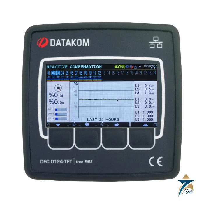
The DFC-0124 is an advanced, precision reactive power controller that works as a 24-step power factor control and metering device. It continuously matches the target cos phi of the load and, thanks to its SVC (static var compensation) outputs, can perform an exact compensation instead of only switching whole capacitor steps. The same unit is a three-phase network analyser: it measures, displays and logs many AC parameters. Datakom describes three SVC outputs that are duty-cycle controlled PWM signals driving three reactors with a precision of 1000 steps, so the controller can supply almost any required reactive power independently of the capacitor-bank selection. In commercial and industrial buildings, workshops and plant rooms where the utility penalises low power factor, a panel-mounted controller of this class sits in the capacitor bank panel next to the main incomer. Related items are in our controllers and data acquisition category.
Technical specifications
| Parameter |
Specification |
| Model |
DFC-0124 reactive power controller (photo shows the TFT display version) |
| Power supply input |
100-265 V AC (+/-15%), 50/60 Hz (+/-10%) |
| Power consumption |
Below 15 VA |
| Supply isolation |
3500 VAC for 1 minute from all other terminals |
| Voltage measurement range |
5-300 V AC (P-N); 10-520 V AC (P-P) |
| Current measurement range |
0.003-6.5 A AC; CT secondary 5 A |
| Frequency range |
30-100 Hz |
| Voltage and current accuracy |
0.5% + 1 digit |
| Frequency accuracy |
0.2% + 1 digit |
| Power accuracy |
1.0% + 2 digits |
| Cos phi accuracy |
0.5% + 1 digit |
| CT range |
5/5 A to 10000/5 A |
| VT range |
0.1/1 to 5000.0/1 |
| kW range |
0.1 kW to 50 MW |
| Harmonic analysis |
Up to the 31st harmonic (voltage and current) |
| Voltage / current burden |
Below 0.1 VA per phase / below 0.5 VA per phase |
| Current input overload |
100 A AC for 1 second |
| Relay outputs |
5 A at 250 V AC; max. switching power 1250 VA; isolation 2000 VAC |
| Static contactor (thyristor) outputs |
PNP transistor, 50 mA at 12 VDC, electronic fuse; 2 units max. in parallel |
| SVC outputs |
3, duty-cycle PWM, 50 mA at 12 VDC |
| Temperature input |
PT100 sensor or switch (selectable) |
| RS-485 |
Isolated (1000 VAC), Modbus RTU, 2400-115200 baud; up to 32 devices per bus; 1200 m at 9600 baud |
| Ethernet |
10/100 Base-TX RJ45, 1500 VAC isolation, max. 30 m |
| USB device / host |
USB 2.0; host for FAT32 flash-memory data recording |
| Operating temperature |
-20 C to +70 C |
| Maximum humidity |
95% non-condensing |
| Protection degree |
IP54 front; IP65 front with gasket; IP30 rear |
| Dimensions (W x H x D) |
164 x 164 x 69 mm |
| Panel cut-out |
140 x 140 mm |
| Weight |
500 g |
EU directives listed in the manual: 2006/95/EC (LVD) and 2004/108/EC (EMC), with EN 61010 (safety) and EN 61326 (EMC) as norms of reference.
Automatic setup, steps and communication
Auto setup is the main commissioning aid. During it the device detects phase order, detects current transformer polarity and order, performs automatic correction of connection faults, and measures and records the type and rating of each step output. For success the voltage inputs must be connected to a three-phase network and the first few outputs must be connected to the three-phase capacitors. Setup is preferably done at no load, although it can be done under stable load; fast-varying loads can cause inaccurate detection, in which case the setup should be repeated and the measured step ratings compared with the real capacitor or reactor banks and adjusted from the front panel if needed. The manual also warns that mixed-up CT polarity or phase order gives false power readings, with worked examples in which a reversed CT turns 300 kW into 100 kW.
- Step options: 24, 18 or 12 step outputs; all steps can drive contactors or thyristors; reactive power correction in 20 ms; compensation on low current (3 mA); separate target cos phi for generator operation.
- Communication: internal Ethernet, optional internal GPRS modem, isolated RS-485 Modbus RTU, RS-232 for an external GPRS modem, Modbus TCP/IP, UDP, SNTP, SNMP, SMTP, TCP/IP server and client, dynamic DNS, embedded website, GSM SMS and e-mail sending.
- Software: Windows-based Rainbow Plus for programming over USB, RS-485, Ethernet and GPRS, and Rainbow Scada for monitoring an unlimited number of devices from one location; firmware upgrade through USB is free of charge.
- Data: user-configurable screens and relay outputs, and recording to a USB flash drive that starts as soon as the drive is inserted.
Ordering code and installation notes
The ordering code in the manual is DFC-0124 followed by the number of steps (12, 18 or 24), the output type (R for relay or T for thyristor), C for the communication option (Ethernet, USB host, USB device, RS-232), M for the internal GSM-GPRS modem, and the display size (2.9 inch black-and-white, or 4.3 or 5 inch). State all of these in your enquiry. The spare mounting brackets are listed with stock codes J10P01 (screw type) and K16P01 (self-retaining type), each per unit.
Safety rules from the manual: installation by a qualified specialist only; fast-type fuses of maximum 6 A on the supply and on the phase voltage inputs, close to the unit; short-circuit the terminals of unused current transformers; disconnect all power before working; and do not connect the same current transformer to other instruments. Choose CTs with low load and class 0.5 for the best accuracy, because the CT phase shift affects power factor readings. Terminate both ends of an RS-485 bus with 120 ohm resistors, and ground the cable shield at one end only. Mount the unit flush in the 140 x 140 mm opening and fit the gasket if IP65 is needed.
Selection and installation notes
A power factor controller is selected from the number of capacitor steps, the CT ratio and the network conditions. Mount the CT on the incomer so it sees the total load current, check the phase and polarity relationship between the CT and the voltage tapping, run the automatic set-up so the controller learns the step sizes and set the target power factor to suit the utility tariff. Check the capacitor currents and the step switching after commissioning.
Information needed for a quotation
Send the full model code, the quantity, the delivery location in Oman or the GCC, the intended use and any accessories needed, so that the complete package can be quoted together.
Documents and supply information
The manufacturer data sheet is attached to this page and should be read together with the project specification and the site risk assessment before a purchase is confirmed. Ratings, standards and dimensions are quoted as printed on that sheet. Lead time, stock position and certificates available with the shipment are confirmed in the quotation, and we supply to Oman and the wider GCC region for industrial, utility and building services projects.
Documents and quotation
The Datakom DFC-0124 user manual (59 pages, version 01, firmware V-4.7) is attached. Send the required step count, output type, communication option and display size so we can quote the right version.







Reviews
There are no reviews yet.