Eight 4-20 mA outputs in a single slot
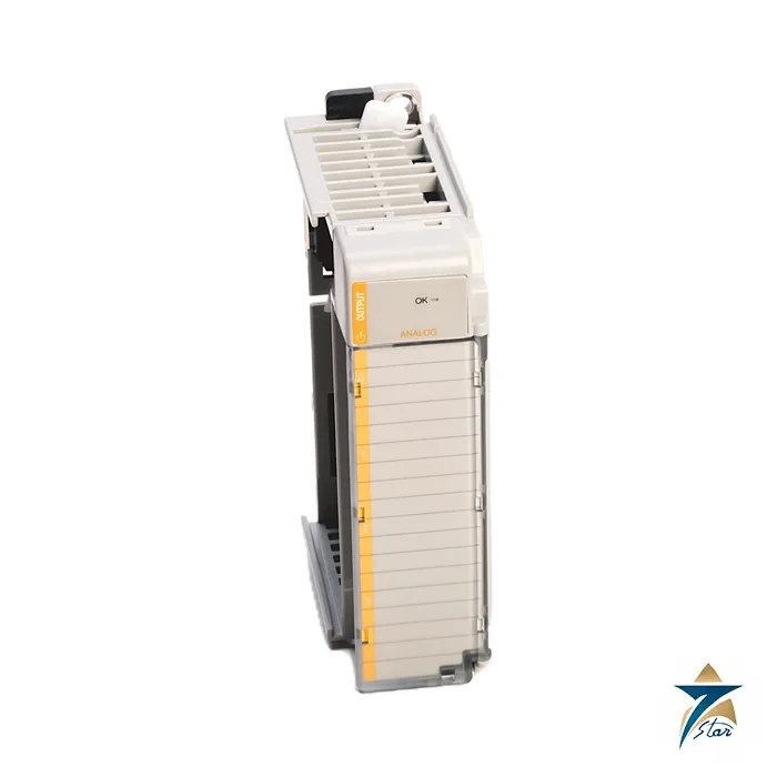
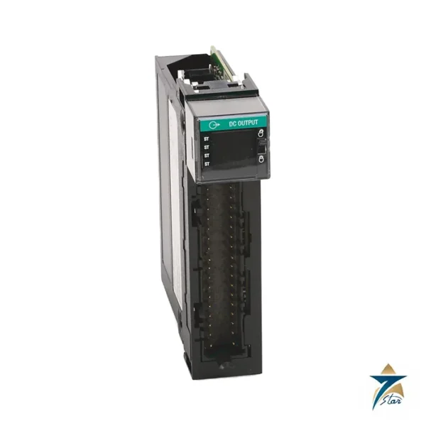
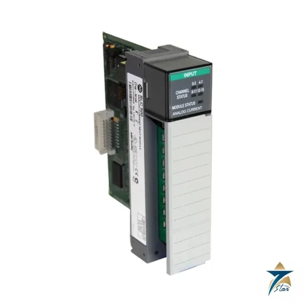
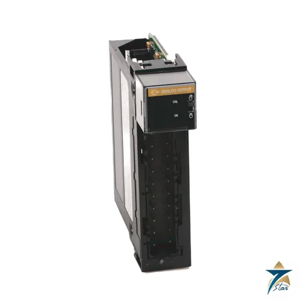
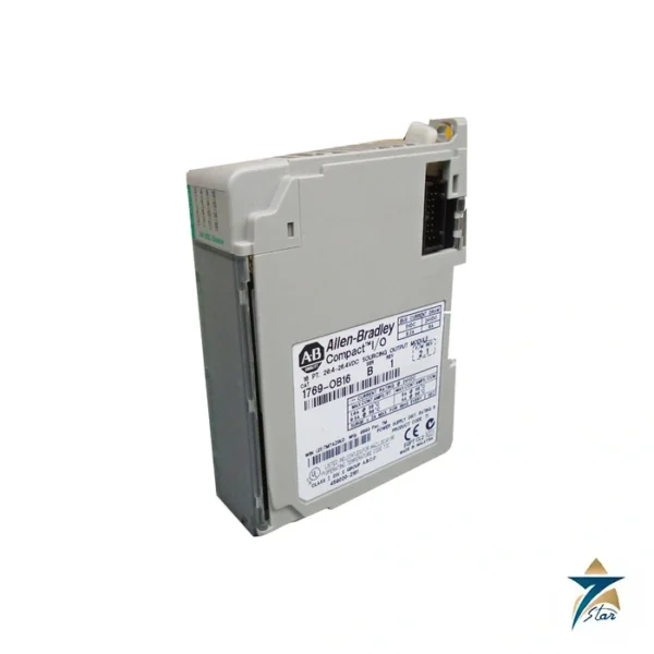
The Allen-Bradley 1769-OF8C is a high-density current output module for Compact I/O. It gives eight single-ended 0-20 mA or 4-20 mA outputs in one 35 mm slot, which suits control valves, I/P converters and drive speed references where each loop is a 4-20 mA signal. Doubling the channel count of the four-channel 1769-OF4 reduces the space and cost per loop.
Resolution is 16 bits, equal to 0.323 microamperes per bit, with accuracy of ±0.35 percent of full scale at 25 °C and ±0.0058 percent per °C drift. All eight channels update within 5 ms, and the step response is below 2.9 ms.
Technical specifications
| Parameter |
Specification |
| Catalog number |
1769-OF8C |
| Module type |
Compact I/O 8-channel current analog output |
| Outputs |
8 single-ended |
| Output ranges |
0…20 mA, 4…20 mA; full-scale 0…21 mA and 3.2…21 mA |
| Resolution |
16 bits; 0.323 µA per bit (15.91 bits on 0…20 mA, 15.59 bits on 4…20 mA) |
| Conversion rate (all channels) |
5 ms maximum |
| Step response to 63% |
Less than 2.9 ms |
| Load |
0…500 Ω including wire resistance; inductive load 0.1 mH maximum |
| Accuracy at 25 °C |
±0.35% full scale; drift ±0.0058% per °C; nonlinearity ±0.05%; module error ±0.55% |
| Output impedance |
Greater than 1 MΩ |
| Protection |
Open and short-circuit protection; 21 mA maximum short-circuit current; overvoltage protection |
| Output at power up/down |
±0.5V DC spike for less than 5 ms |
| Backplane current |
145 mA at 5V DC; 185 mA at 24V DC (0 mA with optional external 24V supply, series B and later) |
| Optional external supply |
24V DC Class 2, 20.4…26.4V DC, 60 mA minimum |
| Heat dissipation |
2.69 W maximum |
| Isolation |
500V AC or 710V DC for 1 minute, output group to bus |
| Data words |
11 input, 9 output, 64 configuration; product code 40 |
| Weight |
281 g (0.62 lb) |
| Mounting / slot width |
DIN rail or panel; 1 slot; 118 x 35 x 87 mm (4.65 x 1.38 x 3.43 in.), height with mounting tabs 138 mm |
| Power supply |
1769-PA2, 1769-PB2, 1769-PA4 or 1769-PB4; power supply distance rating 8 modules |
| Wiring |
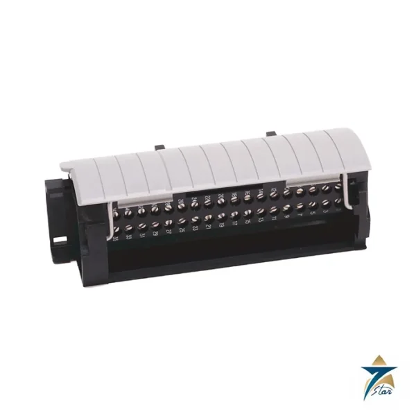
22…14 AWG solid or 22…16 AWG stranded copper, 90 °C; terminal screw torque 0.68 N•m; replacement terminal block 1769-RTBN18 |
| Environment |
Operating 0…60 °C (32…140 °F); non-operating -40…+85 °C; humidity 5…95% non-condensing; open-style enclosure |
| Certifications (when marked, as printed) |
c-UL-us (UL Class I Division 2 Groups A,B,C,D), UKCA and CE (EMC, RoHS), RCM, KC, Morocco |
Power budget and optional external supply
The 1769-OF8C draws 145 mA at 5 V DC and 185 mA at 24 V DC from the 1769 backplane, a significant 24 V load. Series B and later modules support an optional external 24 V DC Class 2 supply of 20.4 to 26.4 V DC with at least 60 mA. When that supply is used, the module takes no 24 V DC current from the bus, which is useful in racks with several analog modules and a small power supply.
Each loop can drive up to 500 ohms including the wire resistance, with inductive loads limited to 0.1 mH. The outputs are protected against open and short circuit, with short-circuit current held at 21 mA. At power up and power down the outputs can spike by ±0.5 V DC for less than 5 ms.
1769-OF8C compared with other analog outputs
The 1769-OF8V in the same specification gives eight voltage outputs, the 1769-OF4 gives four mixed voltage and current outputs, and the isolated 1769-OF4CI gives four individually isolated current outputs. Choose the OF8C when all outputs are current loops and the rack has limited space.
Installing the 1769-OF8C in a Compact I/O rack
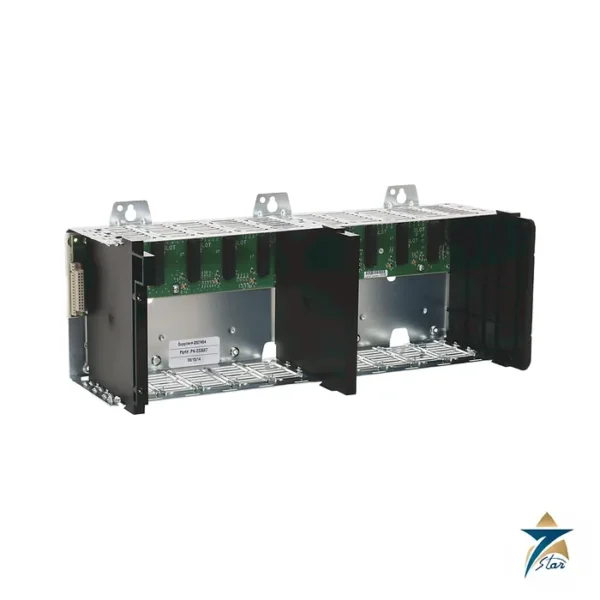
Because the module has an open-style enclosure, it must be installed inside a cabinet that protects it from dust, moisture and accidental contact. Mount the rack on a DIN rail or panel with the clearance around it that the Rockwell installation instructions give for ventilation, and place the module within the distance rating of the power supply. Count the 5 V and 24 V current draw of every module in the bank before adding the OF8C; if the budget is tight, the optional external 24 V supply described above removes its 24 V load from the bus.
Use twisted-pair screened cable for each current loop, ground the screen at one end only as the wiring instructions describe, and keep analog cables separated from motor, drive and contactor wiring. Tighten terminal screws to the listed torque and label each channel to match the loop drawing, which makes later fault-finding much faster.
Configuring and testing the eight outputs
Each channel is configured in the controller project for its range, data format and the state it should take if the controller goes to program mode or faults. Choose these fault and program states deliberately for every loop: a control valve may need to close, hold its last position or open, depending on the process, and the setting should be agreed with the process engineer. During loop checks, write known values from the controller and confirm the current at the field device with a calibrated meter at several points across the range. Check that the total loop resistance, including long cable runs to remote valves, stays within the load rating so that the output can reach full scale.
Selection checks
- All field devices accept current signals; voltage or isolated loops point to the other modules compared on this page.
- Series of the module if the optional external 24 V supply is part of the design.
- Power supply capacity and position of the module in the bank.
Analog outputs in Oman and GCC control panels
Analog modules are sensitive to heat inside the cabinet, and panels in Omani process plants, water facilities and outdoor skids can become very warm in summer. Keep the air temperature inside the enclosure within the operating range listed above, using cooling or ventilation sized for all the heat sources in the panel. Fine dust on the module and terminals, combined with humid coastal air, can lead to leakage paths and corrosion over time, so seal cable entries, keep cabinet doors closed and clean panels during shutdowns with the power isolated. Avoid condensation, which the module specification excludes, by controlling cabinet humidity in locations where equipment cools down at night. Periodic loop checks against the field devices confirm that output accuracy is still adequate for the process.
Documents and quotation
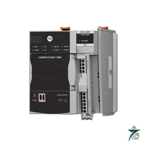
The Rockwell Automation 1769 Compact I/O specifications document is attached. See our PLC and I/O cards category for related controllers, such as the 5069-L320ER controller. Confirm the exact catalog number, series letter and firmware or hardware revision on the product label, and the compatibility with your existing system, before ordering. Stock and lead time are confirmed at quotation.




Reviews
There are no reviews yet.